background image

9

STANDARD OR ANGLE MOUNTING INSTRUCTIONS

1.  Remove the downrod pin (B) and downrod clip (C) from 

the downrod (A). Then partially loosen the set screws 

(R) in the yoke at the top of the motor assembly (G).

2.  Insert the downrod (A) through the canopy (E) and yoke 

cover (O). Feed the wires and braided cable from the 

motor assembly (G) through the downrod (A).

3.  Slide the downrod (A) into the yoke of the motor 

assembly (G), align the holes, then re-install the 

downrod clip (C) and downrod pin (B). Secure with set 

screws (R) and slide the yoke cover (O) down until it 

rests on top of the motor assembly (G). 

A

R

B

C

2

E

A

O

G

3

A

C

R

B

G

1

Yoke

Braided Cable

Summary of Contents for BIRCHMOUNT COVE 41554

Page 1: ...ent at 1 800 643 0067 8 a m 8 p m EST Monday Sunday ATTACH YOUR RECEIPT HERE Purchase Date _________________________ Harbor Breeze is a registered trademark of LF LLC All Rights Reserved AR19040 H arbor Bree z e H arbor Bree z e ITEM 0888518 4105033 BIRCHMOUNT COVE CEILING FAN MODELS 41554 Français p 21 ...

Page 2: ...rmation 5 Preparation 6 Initial Installation 7 Standard or Angle Mounting Instructions 9 Secondary Hanging System 11 Wiring 12 Final Installation 13 Operating Instructions 16 Care and Maintenance 17 Troubleshooting 17 Limited Lifetime Warranty 19 Replacement Parts List 20 ...

Page 3: ...1 G Motor Assembly 1 H Mounting Bracket Screw preassembled to Mounting Bracket D 4 I Motor Screw preassembled to Motor Assembly G 10 J Fitter Plate preassembled to Motor Assembly G 1 K Fitter Plate Screw preassembled to Fitter Plate J 3 L Light Kit 1 M Thumbscrew preassembled to Light Kit L 3 N Glass Bowl 1 O Yoke Cover 1 P Blade Arm 5 Q Blade 5 R Set Screw preassembled to Motor Assembly G 2 S Bul...

Page 4: ...y 15 1 extra Blade Washer Qty 15 1 extra Pull Chain Extension Qty 2 Metal Washer Qty 15 1 extra Secondary Support Screw Qty 1 Support Washer Qty 1 Secondary Spring Washer Qty 1 Hex Nut Qty 15 1 extra Motor Screw 1 extra AA BB CC UU DD VV XX H arbor Bree z e H arbor Bree z e JJ KK MM ...

Page 5: ... loud humming noise from the fan To reduce the risk of fire or electric shock do NOT use a full range dimmer switch to control the fan speed WARNING To reduce the risk of fire electric shock or personal injury mount the fan to an outlet box marked ACCEPTABLE FOR FAN SUPPORT and use the mounting screws provided with the outlet box Most outlet boxes commonly used for the support of lighting fixtures...

Page 6: ... following two conditions 1 this device may not cause interference and 2 this device must accept any interference including interference that may cause undesired operation of the device PREPARATION Before beginning the assembly of this product ensure that all parts are present Compare all parts with the package contents list and hardware contents list If any part is missing or damaged do not attem...

Page 7: ...included Angle style mounting is best suited for angled or vaulted ceilings A longer downrod is sometimes necessary to ensure proper blade clearance Note If using the angle mount check to ensure the ceiling angle is not steeper than 16 Closemount style mounting is not available for this item Flushmount installation is not available for this item 3 Ensure the blades Q will be at least 30 in from an...

Page 8: ...AUTION It is very important to use the proper hardware when installing the mounting bracket D as this will support the fan Important If using the angle mount ensure the open end of the mounting bracket D is installed facing the higher point of the ceiling 6 Remove all 10 pre assembled motor screws I from the underside of the motor assembly G using a Phillips head screwdriver Note The slot in the f...

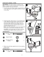
Page 9: ...wnrod A through the canopy E and yoke cover O Feed the wires and braided cable from the motor assembly G through the downrod A 3 Slide the downrod A into the yoke of the motor assembly G align the holes then re install the downrod clip C and downrod pin B Secure with set screws R and slide the yoke cover O down until it rests on top of the motor assembly G A R B C 2 E A O G 3 A C R B G 1 Yoke Brai...

Page 10: ...2 in of insulation from the end of the white wire Twist the stripped ends of each strand of wire within the insulation with pliers not included Repeat this step for black and blue wires Important If you did not cut back the lead wires in Step 4 Step 5 is not necessary and you may proceed to Step 6 6 Install the ball end of the downrod A into the opening of mounting bracket D Align one of the four ...

Page 11: ...aided cable around the secondary support screw JJ Note The ceiling support brace may not be accessible from below If not it must be accessed from above Important The braided cable must make a complete circle around the support brace to secure the fan Hardware Used JJ Secondary Support Screw x 1 Support Washer x 1 Secondary Spring Washer x 1 3 Tighten the secondary support screw JJ securing the bra...

Page 12: ...lack supply wire Secure all wiring connections together with wire connectors AA Note If there is a second hot power wire coming from the outlet box connect it to the Blue light power fan wire for separate light and fan control Note The Blue fan wire is power for the light The Black wire is power for the fan The White wire is common neutral The Green wire is the ground wire If supply wires are diff...

Page 13: ...et screws H previously removed Step 4 page 8 Tighten all mounting bracket screws H securely 3 Partially insert the blade screws BB along with the blade washers CC through the blade Q and blade arm P Place the metal washer UU over the end of the blade screw BB and secure with a hex nut VV Repeat this step for the remaining blades Q and blade arms P Hardware Used BB Blade Screw x 15 Blade Washer x 1...

Page 14: ...tter plate J allows a Phillips screwdriver access to motor screws I 5 Remove the three fitter plate screws K from the fitter plate J Then connect the 9 pin connector from the fitter plate J to the 9 pin connector from the light kit L Note Align the notch in the fitter plate J with the reverse switch on the light kit L 6 Secure the light kit L to the fitter plate J using the three fitter plate scre...

Page 15: ...by turning them counterclockwise Lift the glass bowl N onto the light kit L and reinstall the thumbscrew M Tighten all three thumbscrews M 9 Attach the pull chain extensions DD to the pull chains Note When facing the reverse switch the fan pull chain is on the left and the light pull chain is on the right Hardware Used DD Pull Chain Extension x 2 Turn on power supply to the fan Assembly is complet...

Page 16: ... in your comfort In warmer weather push the reverse switch left to display a sun icon which will result in downward airflow creating a wind chill effect Fig 2a In cooler weather push the reverse switch right to display a snowflake icon which will result in upward airflow that can help move hot air off the ceiling area Fig 2b Important Wait for the fan to stop before moving the reverse switch The r...

Page 17: ...e switch completely left or right 2 Make sure the wall switch is turned on 3 Turn the power on or check the fuse breaker 4 Turn the power off and check all connections at the ceiling outlet box There is excessive wobbling 1 The blades and or blade arms are loose 2 The blades are unbalanced 3 The fan mounting is not secure 4 The fan is too close to the vaulted ceiling 5 The set screws on the motor ...

Page 18: ...o not use a full range dimmer switch to control the fan speed 4 Ensure the outlet box is secured to the building structure 5 Ensure the mounting bracket is secured to the outlet box and that the screws are tight The fan operates correctly but the lights are not working 1 The bulbs are not installed correctly 2 The light kit wire plugs are not connected properly 3 There is a faulty wire connection ...

Page 19: ... varying climate conditions this warranty does not cover any changes in brass finish including rusting pitting corroding tarnishing or peeling Brass finishes of this type give their longest useful life when protected from varying weather conditions Any glass provided with this fan is not covered by the warranty Any replacement of defective parts from the ceiling fan must be reported within the fir...

Page 20: ... 4L000012390 L Light Kit 4L000012360 N Glass Bowl 4A162960001 O Yoke Cover 4L000012370 P Blade Arm x 5 4A070220017 Q Blade x 5 4L080200002 HW Hardware Kit 4L000012400 9568PB 122619 D E A F L N O HW P Q REPLACEMENT PARTS LIST For replacement parts call the customer service department at 1 800 643 0067 8 a m 8 p m EST Monday Sunday ...

Reviews: