background image

19

Printed in China

REPLACEMENT PARTS LIST

For replacement parts, call our customer service department at 

1-800-643-0067

, 8 a.m. - 6 p.m., EST, 

Monday - Thursday,  8 a.m. - 5 p.m., EST, Friday.

    PART                 DESCRIPTION 

          PARTS#                 


A


Downrod


B


Canopy


C


Mounting Bracket


E


Yoke Cover


F


Blade


I


Motor Screw


K


Lock Washer


L


Canopy Mounting Screw


M


Pin


N


Clip

 O  Glass 

Shade

 P  Star 

Washer

 AA  Blade 

Screw

  BB 

Fiber Blade Washer

 CC


E3 Wire Connector

LI1307

Harbor Breeze® is a registered trademark

 of LF, LLC. All Rights Reserved.

Lowes.com/harborbreeze

E

F

N

B

C

A

I

M

K

L

CC

AA

BB

P

276094-A
276094-B
276094-C
276094-E
276094-F
276094-I
276094-K
276094-L
276094-M
276094-N
276094-O
276094-P
276094-AA
276094-BB
276094-CC

O

Summary of Contents for AERO CEILING FAN E-AER52BRZ5LKRCI

Page 1: ...ns require ceiling fans with light kits manufactured or imported after January 1 2009 to limit total wattage consumed by the light kit to 190W Therefore this fan is equipped with a wattage limiting device Questions problems missing parts Before returning to your retailer call our customer service department at 1 800 643 0067 8 a m 6 p m EST Monday Thursday 8 a m 5 p m EST Friday EB13825 Lowes com ...

Page 2: ...andbook if you are unfamiliar with installing electrical wiring Make sure the installation site you choose allows a minimum clearance of 7 ft from the blades to the floor and at least 30 in from the end of the blades to any obstruction After you install the fan make sure that all connections are secure to prevent the fan from falling The net weight of this fan including the light kit is 21 54 lbs ...

Page 3: ... of the fan at least 35 lbs Do NOT use a plastic outlet box To avoid personal injury the use of gloves may be necessary while handling fan parts with sharp edges To reduce the risk of fire electrical shock or personal injury wire connectors provided with this fan are designed to accept only one 12 gauge house wire and two lead wires from the fan If your house wire is larger than 12 gauge or there ...

Page 4: ...ng Bracket 1 D Motor Housing 1 E Yoke Cover 1 F Blade 5 G Remote Control Transmitter 1 H Remote Control Receiver 1 I Motor Screw 6 preassembled DESCRIPTION PART QUANTITY J Bulb 1 K Lock Washer 6 preassembled DESCRIPTION PART QUANTITY M Pin preassembled 1 N Clip preassembled 1 O Glass Shade 1 P Star Washer 4 preassembled Q Battery 1 A N M O L Canopy Mounting Screw 4 preassembled LOW MED HIGH P Q ...

Page 5: ...e building structure and can support the full weight of the fan Failure to do this can result in serious injury or death The stability of the outlet box is essential in minimizing wobble and noise in the fan after installation is complete CAUTION Be sure outlet box is properly grounded and that a ground wire green or bare is present After opening top of carton remove mounting hardware package from...

Page 6: ... injury or death 1 INITIAL INSTALLATION ON OFF ON OFF 1 Lowes com harborbreeze 3 Check to make sure blades F are at least 30 in from any obstruction and at least 7 ft above the floor 3 F 7 ft min 30 in min 2 A 2 Determine mounting method to use A Standard mount B Angle mount IMPORTANT If using the angle mount ensure the ceiling angle is not steeper than 19 B ...

Page 7: ...t C to outlet box not included using screws spring washers and flat washers provided with the outlet box NOTE It is very important you use the proper hardware when installing the mounting bracket C as this will support the fan IMPORTANT If using the angle mount make sure open end of mounting bracket C is installed facing the higher point of the ceiling 4b C 4b 4a C L B P 5 5 Remove motor screws I ...

Page 8: ...t on each blade screw AA prior to installing blades F 3 F 2 Slot E Center Band Hardware Used Blade Screw x 15 AA Fiber Blade Washer x 15 BB AA BB Replace top of motor housing D and yoke plate and secure with motor screws I and lock washers K that were previously removed Step 5 page 7 IMPORTANT Circular cutout on motor housing D and yoke plate should line up over electrical wiring and the opening f...

Page 9: ...gs 8 ft high or higher For taller ceilings you may want to use a longer downrod not included Angle style mounting is best suited for angled or vaulted ceilings A longer downrod is sometimes necessary to ensure proper blade clearance Set Screw 4a N D M 4a 4b A 4b A B E 6 Slip downrod A into motor housing yoke align holes and re install pin M and clip N Tighten set screws in motor housing yoke and t...

Page 10: ...e following manner Take the lead wires and make sure you have pulled them all the way through the top of the downrod Start at the TOP of the ball on the downrod and measure 8 in of lead wire and then cut the excess wire off with wire cutters not included NOTE If you do not cut back the lead wires Steps 7 and 8 are not necessary and you may proceed to Step 9 instead Ball 7 7 O If you decided to cut...

Page 11: ...fessional electrician is recommended to determine wiring NOTE Black and blue wires are hot power for fan White wire is common for fan Green or bare wire is ground Make the necessary wiring connections for remote control operation according to drawing at right For each wire connection use one of the wire connectors CC making sure to screw wire connector CC on in a clockwise direction Make sure to c...

Page 12: ...connectors AA into outlet box Let antenna from remote control receiver H hang to the side NOTE The remote control included with this fan meets the following requirements a Not for use with solid state fans b Electrical rating 120V 60 Hz motor amps 1 25 MAX light watts 300 Incandescent only Should you choose to use a different remote control with this fan it must also meet these same requirements 3...

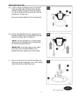
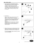
Page 13: ...mind not to touch the bulb itself as described above J Align openings in grooves of glass shade O with nodules on underside of motor housing D Turn glass shade O clockwise until it no longer turns Pull down very gently on glass shade O to ensure it is securely attached 3 O D 1 Lift canopy B to mounting bracket C and align slotted holes in canopy B with loosened canopy mounting screws L in mounting...

Page 14: ...tment Dimmer switch has been pre set to the ON position DIM Note If you prefer not to have dimming capability set the dimmer switch to the OFF position ON OFF Place battery Q in battery compartment and then replace battery cover on back of remote control transmitter G 3 AUTOMATED LEARNING PROCESS ACTIVATING CODE Remove battery cover from back of remote control transmitter G Locate battery Q in har...

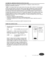
Page 15: ...wing measures Reorient or relocate the receiving antenna Increase the separation between the equipment and receiver Connect the equipment into an outlet on a circuit different from that to which the receiver is connected Consult the dealer or an experienced radio TV technician for help OPERATING INSTRUCTIONS 1 1 Light Button Brightness Readout Fan Button Operation buttons on the panel of the remot...

Page 16: ...2b In cooler weather setting the reverse switch in the RIGHT position will result in upward airflow that can help move stagnant hot air off the ceiling area 2a 2b OPERATING INSTRUCTIONS 2 Use the fan reverse switch located on top of the motor housing D to optimize the fan for seasonal performance A ceiling fan will allow you to raise your thermostat setting in summer and lower your thermostat sett...

Page 17: ...r right 2 Turn power on or check fuse 3 Turn power off Loosen canopy and check all connections Noisy operation 1 Blades are loose 2 Cracked blade 3 Full range dimmer switch 4 Fan is new 1 Tighten all blade screws 2 Replace blade 3 Replace with an approved speed control device 4 Allow fan a break in period of a few days especially when running the fan at Medium and High speeds Excessive wobbling 1 ...

Page 18: ...d within the first year from the date of purchase For the balance of the warranty call our customer service department at 1 800 643 0067 for return authorization and shipping instructions so that we may repair or replace the ceiling fan Any fan or parts returned improperly packaged is are the sole responsibility of the purchaser There is no further express warranty The distributor disclaims any an...

Page 19: ...Yoke Cover F Blade I Motor Screw K Lock Washer L Canopy Mounting Screw M Pin N Clip O Glass Shade P Star Washer AA Blade Screw BB Fiber Blade Washer CC E3 Wire Connector LI1307 Harbor Breeze is a registered trademark of LF LLC All Rights Reserved Lowes com harborbreeze E F N B C A I M K L CC AA BB P 276094 A 276094 B 276094 C 276094 E 276094 F 276094 I 276094 K 276094 L 276094 M 276094 N 276094 O ...

Reviews: