


12
13
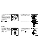
FINAL INSTALLATION
7
7. If you want to use the light kit (J), connect male plug
from motor housing assembly (G) to the female plug
from switch housing (I).
WARNING
should be turned off prior to the removal of the light kit.
G
I
Female
plug
Male plug
8. Attach switch housing (I) to switch housing cover (H).
Align switch housing (I) holes with switch housing
cover (H) holes. Install the previously removed screws
(Step 6, page 12) and tighten securely.
Note:
The wider gap in the edge of the switch housing
cover (H) should align with reverse switch on the switch
housing (I).
9. Install bulbs (L) into sockets.
Note
: The fan has an energy-saving wattage limiter
included. If candelabra-base bulbs are over 190
watts, light will automatically turn off. Please ensure
bulb wattage is always below 190 watts.
FINAL INSTALLATION
8
I
Screw
H
9
L
10. Remove preassembled rubber washer, hex nut,
10
M
N
Hex Nut
Rubber
Washer
J
Lowes.com/harborbreeze
Lowes.com/harborbreeze
6. Remove preassembled screws from the switch housing
cover (H).
If using fan WITH the light kit, continue to Step 7.
If using fan WITHOUT the light kit, proceed to Step 14.
Screw
H
6
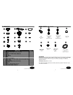
Hardware Used
5. Attach blade bracket (E) to motor housing assembly (G)
with two blade bracket screws and washers (GG). Securely
tighten blade bracket screws and washers (GG). Repeat for
remaining blade assemblies.
5
Blade Bracket Screw with
Washer
x 8
GG
E
G
GG


