Harbor Breeze AERO 00980 Installation Manual Download Page 4

6

7

INITIAL INSTALLATION

IMPORTANT

: If angle mounting, make sure open end of 

mounting bracket (A) is installed facing the ceiling.

Depending on the mounting method (A or B)  

chosen in Step 1, either proceed to page 7 for  

“DOWNROD-STYLE MOUNTING” or proceed to 


page 8 for “CLOSEMOUNT-STYLE MOUNTING.”

DOWNROD-STYLE MOUNTING

1. Determine mounting method.

    A-Downrod Mount (standard or angled ceiling) 

    B-Closemount (standard ceiling only)


IMPORTANT:

 If angle mounting, check to make 

    sure the ceiling angle is not steeper than 20°.

3.  Install mounting bracket (A) to outlet box (not included) 

by sliding mounting bracket (A) over the two outlet box 

screws (not included). Securely tighten two outlet box 

screws. 

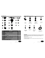
2.  Remove two non-slotted screws on canopy (B) and 

save, then loosen the two slotted screws. Remove 

mounting bracket (A) from canopy (B).

1

1

2

2.  Insert downrod (D) through canopy (B) and canopy

     cover (C). Thread wires from motor housing

     assembly (G) through downrod (D).

1.   Remove preassembled pin and clip from  

downrod (E). Save for later use.


2

A

Outlet  box    

Clip  

Pin     

E

C

D

B

Loosen but do 

not remove

Remove 

and save

A

B

3

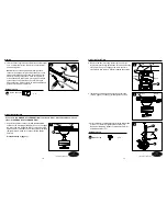
3.  Loosen preassembled set screws from the yoke on 

motor housing assembly (G). Slip downrod (D) into yoke, 

aligning holes on both parts. Insert previously removed 

pin through holes on yoke and downrod (D), then insert 

previously removed clip into the pin until it snaps into 

place. Tighten set screws.   

Set  screw  

D

G

Clip  

Pin  

3

Lowes.com/harborbreeze    

Lowes.com/harborbreeze    

A

B

Summary of Contents for AERO 00980

Page 1: ...caci n de accesorios de fabricante no asume ning n tipo de responsabilidad por la instalaci n del ventilador durante la garant a limitada de por vida Cualquier servicio realizado por una persona no au...

Page 2: ...ZARD To reduce the risk of electric shock do not use this fan with any solid state speed control device ELECTRIC SHOCK HAZARD To reduce the risk of electric shock make sure electricity has been turned...

Page 3: ...re strippers PREPARATION L N Fan Pull Chain Extension Qty 1 NOT TO SCALE Light Pull Chain Extension Qty 1 NOT TO SCALE EE FF GG Blade Screw Qty 13 Rubber Gasket Qty 1 NOT TO SCALE M HH Plastic Plug Qt...

Page 4: ...ws not included Securely tighten two outlet box screws 2 Remove two non slotted screws on canopy B and save then loosen the two slotted screws Remove mounting bracket A from canopy B 1 1 2 2 Insert do...

Page 5: ...upler screws EE Securely tighten screws 3 EE Coupler Screw with Washer x 3 HH G B EE Coupler Hardware Used 2 Place rubber gasket HH into the coupler on motor housing assembly G Pull wires through hole...

Page 6: ...s previously removed Step 2 page 6 to canopy B and tighten securely Proceed to Step 4 page 11 1 Outlet box Screw B 4 Attach blade F to blade bracket E using three blade screws FF Securely tighten blad...

Page 7: ...kets Note The fan has an energy saving wattage limiter included If candelabra base bulbs are over 190 watts light will automatically turn off Please ensure bulb wattage is always below 190 watts FINAL...

Page 8: ...Step 10 page 13 onto the pipe and securely tighten Pass fan pull chain through side hole on bowl cap M securely tighten 12 M N Hardware Used Fan Pull Chain Extension x 1 BB Light Pull Chain Extension...

Page 9: ...light fixture either ON or OFF with each pull the chain 2 REVERSE SWITCH When the season changes you may want to change the direction the fan spins To switch between clockwise and counterclockwise ro...

Page 10: ...y implied warranty which can not be disclaimed is limited to the lifetime limited or special damages arising at or in connection with product use or performance except as may rights which vary from st...

Reviews: