background image

17

Lowes.com/harborbreeze

CARE AND MAINTENANCE

At least twice each year, lower the canopy to check the downrod assembly, and then tighten all 

screws on the fan . Clean the motor housing with only a soft brush or lint-free cloth to avoid scratching 

the finish. Clean the blades with a lint-free cloth. 

Bulb Replacement: Use 40-watt max . candelabra-base bulbs or CFL equivalent .

Immortant:

 Shut off the main power supply before you begin any maintenance tasks. Do not use 

water or a damp cloth to clean the ceiling fan .

TROUBLESHOOTING

PROBLEM

POSSIBLE CAUSE

CORRECTIVE ACTION

The fan does not 

move .

1 . 

The power is off or the fuse is 

blown .

2 .  There is a faulty wire connection .
3 .  The plugs are not connected 

properly .

4 .  The reverse switch is not 

completely engaged .

1 .  Turn the power on or check the 

fuse .

2 . 

Turn the power off. Loosen the 

canopy and check all connections .

3 .  Check that the connectors from 

the light kit fitter and fan are 

connected properly .

4 .  Push the reverse switch 

completely to the left or right .

The fan is noisy .

1 .  The blades are loose .
2 .  There is a cracked blade .
3 .  The wall control is not compatible 

with the fan .

4 .  The outlet box is not secure .
5 .  The mounting bracket is not 

secure .

1 .  Check and tighten all screws that 

hold the fan blades to the blade 

arms and the motor .

2 .  Replace the cracked blade .
3 .  Do not use a full range dimmer 

switch to control the fan speed .

4 .  Ensure the outlet box is secured 

to the building structure .

5 .  Ensure the mounting bracket is 

secured to the outlet box and that 

the screws are tight .

Summary of Contents for 40661

Page 1: ...1 800 643 0067 8 a m 6 p m EST Monday Thursday 8 a m 5 p m EST Friday 1 Lowes com harborbreeze Harbor Breeze is a registered trademark of LF LLC All Rights Reserved ATTACH YOUR RECEIPT HERE Purchase...

Page 2: ...Hardware Contents 4 Safety Information 5 Preparation 6 Initial Installation 7 Secondary Hanging System 11 Wiring 12 Final Installation 13 Operating Instructions 16 Care and Maintenance 17 Troubleshoot...

Page 3: ...t 1 E Canopy 1 F Canopy Cover 1 G Motor Assembly 1 H Light Kit preassembled to the Motor Assembly G 1 I Yoke Cover 1 J Bulb 2 K Glass Bowl 1 L Blade Arm 4 M Blade 4 N Motor Screw preassembled to the M...

Page 4: ...tra Blade Screw Qty 12 1 extra Blade Washer Qty 12 1 extra Screw Cap Qty 12 1 extra Pull Chain Extension Qty 2 Secondary Support Screw Qty 1 Support Washer Qty 1 Secondary Spring Washer Qty 1 FF GG HH...

Page 5: ...full range dimmer switch to control the fan speed WARNING To reduce the risk of fire electric shock or personal injury mount the fan to an outlet box marked ACCEPTABLE FOR FAN SUPPORT and use the moun...

Page 6: ...ing the assembly of this product ensure that all parts are present Compare all parts with the package contents list and hardware contents list If any part is missing or damaged do not attempt to assem...

Page 7: ...uded Angle style mounting is best suited for angled or vaulted ceilings A longer downrod is sometimes necessary to ensure proper blade clearance Important If using the angle mount check to ensure the...

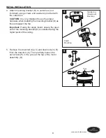
Page 8: ...installing the mounting bracket D as this will support the fan Important If using the angle mount ensure the open end of the mounting bracket D is installed facing the higher point of the ceiling 5 Re...

Page 9: ...nd downrod clip C Secure with set screws P and slide the yoke cover I down until it rests on top of the motor assembly G 8 Depending on the length of downrod you use you may need to cut the lead wires...

Page 10: ...you did not cut back the lead wires in Step 8 Step 9 is not necessary and you may proceed to Step 10 instead 10 Install the downrod A into the opening of the mounting bracket D Align one slot in the...

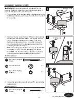
Page 11: ...p of the braided cable around the secondary support screw FF Note The ceiling support brace may not be accessible from below If not it must be accessed from above Important The braided cable must make...

Page 12: ...tral supply wire Connect the Black and Blue wires from the fan to the Black hot supply wire Secure all wiring connections together with wire connectors AA Important The Blue fan wire is power for the...

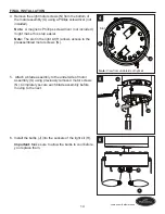
Page 13: ...y screw O into the mounting bracket D 2 Slide the key slots in the canopy cover F over the heads of the canopy screws O preassembled to the mounting bracket D Twist the canopy cover F clockwise to loc...

Page 14: ...ote The slot in the light kit H allows access to the preassembled motor screws N 5 Attach a blade assembly to the underside of motor assembly G using previously removed motor screws N Completely secur...

Page 15: ...into place once installed properly 8 Attach pull chain extensions EE to the pull chains Note When facing the reverse switch on the light kit H the fan pull chain is on the right and the light pull ch...

Page 16: ...t feeling a difference in your comfort In warmer weather push the reverse switch to the left to display a Sun icon which will result in downward airflow creating a wind chill effect Fig 2a In cooler w...

Page 17: ...ection 3 The plugs are not connected properly 4 The reverse switch is not completely engaged 1 Turn the power on or check the fuse 2 Turn the power off Loosen the canopy and check all connections 3 Ch...

Page 18: ...osen the canopy and verify that the mounting bracket is secure to the electrical outlet box The bracket must be flush without movement against the outlet box 4 Use a longer downrod sold separately or...

Page 19: ...alid Due to varying climate conditions this warranty does not cover any changes in brass finish including rusting pitting corroding tarnishing or peeling Brass finishes of this type give their longest...

Page 20: ...T DESCRIPTION 0806201 PART 0806202 PART 0806203 PART A Downrod 0806201 A 0806202 A 0806203 A D Mounting Bracket 0806201 D 0806202 D 0806203 D E Canopy 0806201 E 0806202 E 0806203 E F Canopy Cover 0806...

Reviews: