background image

9

Lowes.com/harborbreeze

STANDARD OR ANGLE MOUNTING INSTRUCTIONS

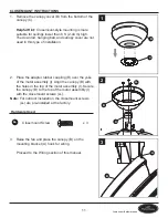
1 .  Remove the downrod pin (DD) and downrod clip 

(EE) from the downrod (E) . Then partially loosen the 

motor housing set screws (FF) in the yoke at the top 

of the motor assembly (I) . 

Haodwaoe Used

DD

Downrod Pin

x 1

EE

Downrod Clip

x 1

FF

Motor Housing 

Set Screw

x 2

I

E

EE

DD

FF

E

1

2 .  Insert the downrod (E) through the canopy (B), 

canopy cover (C), and yoke cover (D) . Thread 

the wires from the motor housing assembly (I) up 

through the downrod (E) and hanger ball rubber 

coupling (S) .  This will prevent water from running 

through the down rod .

E

S

B

C

D

I

2

Summary of Contents for 40094

Page 1: ...your retailer call our customer service department at 1 800 643 0067 8 a m 6 p m EST Monday Thursday 8 a m 5 p m EST Friday 1 ATTACH YOUR RECEIPT HERE Serial Number _________________________ Purchase...

Page 2: ...4 Safety Information 5 Preparation 6 Assembly Instructions 7 Standard or Angle Mounting Instructions 9 Closemount Instructions 11 Wiring 12 Final Installation 14 Operation Instructions 19 Care and Mai...

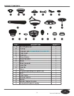
Page 3: ...py 1 C Canopy Cover preassembled to Canopy B 1 D Yoke Cover 1 E Downrod 1 F Blade Bracket 5 G Blade Medallion 5 H Blade 5 I Motor Assembly 1 J Light Pan 1 K Light Kit 1 L Glass 1 M Finial preassembled...

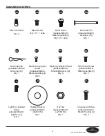
Page 4: ...E Qty 1 Motor Housing Set Screw preassembled to Motor Assembly I Qty 2 Mounting Bracket Screw preassembled to Mounting Bracket A Qty 4 Fitter Plate Screw peassembled to Motor Assembly I Qty 3 II Ligh...

Page 5: ...se a full range dimmer switch to control the fan speed WARNING To reduce the risk of fire electric shock or personal injury mount the fan to an out let box marked ACCEPTABLE FOR FAN SUPPORT and use th...

Page 6: ...at all parts are present Compare all parts with the package contents list and hardware contents list If any part is missing or damaged do not attempt to assemble the product After opening the top of t...

Page 7: ...in serious injury or death 1 2 Determine the mounting method to use Note Flushmount installation is not available for this item Important If using the angle mount check to ensure the ceiling angle is...

Page 8: ...d CC Motor Screw x 10 4 I CC 5 Install the mounting bracket A to the outlet box by sliding the mounting bracket A over the two mounting screws supplied by the outlet box Securely tighten the mounting...

Page 9: ...e at the top of the motor assembly I Hardware Used DD Downrod Pin x 1 EE Downrod Clip x 1 FF Motor Housing Set Screw x 2 I E EE DD FF E 1 2 Insert the downrod E through the canopy B canopy cover C and...

Page 10: ...ssembly I Hardware Used DD Downrod Pin x 1 EE Downrod Clip x 1 FF Motor Housing Set Screw x 2 DD 3 FF E EE I D 4 Install the hanger ball portion on the top of the downrod E into the mounting bracket A...

Page 11: ...Place the adaptor rubber coupling R over the yoke of the motor assembly I Align the canopy B with the holes in the top of the motor assembly I Secure the canopy B to the top of the motor assembly I w...

Page 12: ...wire is present 1 Connect the Black wire from the fan to the Black wire from the ceiling Connect the White wire from the fan to the White wire from the ceiling Connect all Ground Green wires together...

Page 13: ...push the wires and wire connectors AA into the outlet box WARNING Ensure that no bare wire or wire strands are visible after making connections Place the Green and White wire connections on opposite s...

Page 14: ...previously removed mounting bracket screws GG and securely tighten all four screws GG Push the canopy cover C up into the bottom of the canopy B until it is locked Note Closemount installation will n...

Page 15: ...e motor assembly I and save Loosen but do not remove the other two fitter plate screws HH Hardware Used HH Fitter Plate Screw x 3 HH I 5 6 Align the two key slots in the light pan J with the loosened...

Page 16: ...lack wire from the light kit K and connect the white wire from the motor assembly I to the white wire from the light kit K by connecting the plugs 8 I K 9 Align the two key slots in the light kit K wi...

Page 17: ...t kit K Note This fan has an energy saving wattage limiter included in the receiver If you replace the included 40 watt candelabra base bulbs with over 190 watts the fan will automatically turn off Pl...

Page 18: ...breeze FINAL INSTALLATION 13 Align the three indents on the inside of the light frame O with the three raised dimples on the light kit K Turn the light frame O clockwise to hold the light frame on the...

Page 19: ...B In cooler weather push the reverse switch to the right to display a Snowflake icon which will result in upward airflow that can help move stagnant hot air off the ceiling area Important The reverse...

Page 20: ...ceiver stores the light setting when the light is turned off When the light is turned on again it starts with the most recent setting 3 00 0 000 4 Your remote is pre programmed at the factory and will...

Page 21: ...the reverse switch to either the left or right 2 Make sure the wall switch is turned on 3 Turn the power on or check the fuse breaker 4 Turn the power off and check all connections at the ceiling out...

Page 22: ...the electrical outlet box The bracket must be flush without movement against the outlet box 4 Use a longer downrod or move the fan to another location 5 Lift up the yoke cover and tighten the set scr...

Page 23: ...alid Due to varying climate conditions this warranty does not cover any changes in brass finish including rusting pitting corroding tarnishing or peeling Brass finishes of this type give their longest...

Page 24: ...department at 1 800 643 0067 8 a m 6 p m EST Monday Thursday 8 a m 5 p m EST Friday PART DESCRIPTION A Mounting Bracket B Canopy C Canopy Cover D Yoke Cover E Downrod F Blade Bracket G Blade Medallion...

Page 25: ...uestro Departamento de Servicio al Cliente al 1 800 643 0067 de lunes a jueves de 8 a m a 6 p m y los viernes de 8 a m a 5 p m hora est ndar del Este 25 ADJUNTE SU RECIBO AQU N mero de serie _________...

Page 26: ...araci n 30 Instrucciones de ensamblaje 31 Instrucciones est ndares y de montaje en ngulo 33 Instrucciones para montaje cerrado 35 Cableado 36 Instalaci n final 38 Instrucciones de funcionamiento 43 Cu...

Page 27: ...ta 1 C Cubierta de la base preensamblada en la base B 1 D Cubierta de la horquilla 1 E Varilla 1 F Abrazadera del aspa 5 G Medall n del aspa 5 H Aspa 5 I Ensamble del motor 1 J Bandeja de luz 1 K Kit...

Page 28: ...ensamblado en el ensamble del motor I Cant 2 Tornillo para soporte de montaje preensamblado en el soporte de montaje A Cant 4 Tornillo de la placa de soporte preensamblado en el ensamble del motor I C...

Page 29: ...rolar la velocidad del ventilador ADVERTENCIA Para reducir el riesgo de incendios descargas el ctricas o lesiones personales instale el ventilador en una caja de salida marcada como APTA PARA SOSTENER...

Page 30: ...ese de tener todas las piezas Compare todas las piezas con la lista del contenido del paquete y con la lista de aditamentos No intente ensamblar el producto si falta alguna pieza o si estas est n da a...

Page 31: ...es o la muerte 1 2 Determine el m todo de instalaci n que utilizar Nota La instalaci n de montaje al ras no est disponible para este art culo Importante Si realiza el montaje en ngulo verifique que el...

Page 32: ...del motor x 10 4 I CC 5 Instale el soporte de montaje A en la caja de salida deslizando el soporte de montaje A sobre los dos tornillos de montaje que incluye la caja de salida Apriete firmemente los...

Page 33: ...FF que se encuentran en la horquilla de la parte superior del ensamble del motor I Aditamentos utilizados DD Pasador de la varilla x 1 EE Sujetador de la varilla x 1 FF Tornillo de ajuste de la carcas...

Page 34: ...tos utilizados DD Pasador de la varilla x 1 EE Sujetador de la varilla x 1 FF Tornillo de ajuste de la carcasa del motor x 2 DD 3 FF E EE I D 4 Instale la parte superior de la varilla que posee la bol...

Page 35: ...stalaci n 1 C B 2 Alinee la base B con los orificios de la parte superior del ensamble del motor I Fije la base B a la parte superior del ensamble del motor I con los tornillos de montaje cerrado LL N...

Page 36: ...de salida cuente con la puesta a tierra adecuada o de que haya un conductor verde o desnudo de puesta a tierra 1 Conecte el cable negro del ventilador al cable negro del techo Conecte el cable blanco...

Page 37: ...a hacia arriba y empuje suavemente los cables y los conectores de cables AA hacia dentro de la caja de salida ADVERTENCIA Aseg rese de que no haya conductores desnudos ni filamentos de cables visibles...

Page 38: ...nillos del soporte de montaje GG que retir anteriormente y apriete firmemente los cuatro tornillos GG Presione la cubierta de la base C hacia arriba hacia el fondo de la base B hasta que est asegurada...

Page 39: ...nillos de la placa de soporte HH pero no los retire Aditamentos utilizados HH Tornillo de la placa de soporte x 3 HH I 5 6 Alinee los dos chaveteros en la bandeja de luz J con los tornillos de la plac...

Page 40: ...ensamble del motor I al cable blanco del kit de iluminaci n K conectando los enchufes 8 I K 9 Alinee los dos chaveteros del kit de iluminaci n K con los dos tornillos de la abrazadera de la bandeja d...

Page 41: ...lador se incluye un fusible limitador que restringe el voltaje y ahorra energ a Si reemplaza las bombillas de base candelabro de 40 vatios incluidas con el producto por unas de m s de 190 vatios su ve...

Page 42: ...NAL 13 Alinee las tres hendiduras de la parte interna del marco de luz O con las tres protuberancias del kit de iluminaci n K Encienda el marco de luz O en direcci n de las manecillas del reloj para f...

Page 43: ...1B En climas m s fr os deslice el interruptor de reversa hacia la derecha y ver un icono de copo de nieve lo que crear un flujo de aire ascendente que puede ayudar a mover el aire caliente estancado f...

Page 44: ...la intensidad de la luz al apagarla Cuando se vuelve a encender la luz se pone en funcionamiento con el ltimo ajuste establecido 3 00 0 000 4 Su control remoto se preprogram en la f brica y funcionar...

Page 45: ...derecha 2 Aseg rese de que el interruptor de pared est encendido 3 Encienda el suministro el ctrico o verifique el fusible interruptor 4 Desactive la alimentaci n el ctrica y revise todas las conexio...

Page 46: ...ras de la caja de salida y no debe moverse 4 Utilice una varilla m s larga o mueva el ventilador a otra ubicaci n 5 Levante la cubierta de horquilla y apriete el tornillo de ajuste en la horquilla ha...

Page 47: ...arant a Debido a las cambiantes condiciones clim ticas esta garant a no cubre cambios en el acabado de lat n incluidos la oxidaci n las picaduras la corrosi n el deslustre o el descascarado Los acabad...

Page 48: ...vicio al Cliente al 1 800 643 0067 de lunes a jueves de 8 a m a 6 p m y los viernes de 8 a m a 5 p m hora est ndar del Este PIEZA DESCRIPCI N A Soporte de montaje B Cubierta C Cubierta de la base D Cu...

Reviews: