background image

16

Printed in China

GGLI2008

REPLACEMENT PARTS LIST

For replacement parts, call our customer service department at 

1-800-527-1292

, 8:30 a.m. - 5 p.m., CST, 

Monday - Friday.

A

A

Mounting Plate

F

Blade

02807161

-A

02807161

-F

02807160

-A

02807160

-F

02599766

-A

02599766

-F

The distributor warrants this fan to be free from defects in workmanship and materials present at time 
of shipment from the factory for Lifetime limited from the date of purchase.  This warranty applies only 
to the original purchaser. The distributor agrees to correct any defect at no charge or, at our option, 
replace the ceiling fan with a comparable or superior model.

To obtain warranty service, present a copy of your sales receipt as proof of purchase.  All cost of 
removal and reinstallation are the express responsibility of the purchaser.  Any damage to the ceiling 
fan by accident, misuse or improper installation, or by using parts not produced by the manufacturer 
of this fan or affixing accessories not produced by the manufacturer of this fan, are the purchaser's 
own responsibility.  The distributor assumes no responsibility whatsoever for fan installation during 
the limited lifetime warranty.  Any service performed by an unauthorized person will render the 
warranty invalid.

Due to varying climatic conditions, this warranty does not cover changes in brass finish, rusting, 
pitting, tarnishing, corroding or peeling.  Brass finish fans maintain their beauty when protected from 
varying weather conditions.  Any glass provided with this fan is not covered by the warranty.

Any replacement of defective parts for the ceiling fan must be reported within the first year from the 
date of purchase.  For the balance of the warranty, call our customer service department (

at 

1-800-527-1292

)

 for return authorization and shipping instructions so that we may repair or replace 

the ceiling fan.  Any fan or parts returned improperly packaged is/are the sole responsibility of the 
purchaser.  There is no further express warranty.  The distributor disclaims any and all implied 
warranties.  The duration of any implied warranty which cannot be disclaimed is limited to the limited 
lifetime period as specified in our warranty.  The distributor shall not be liable for incidental, 
consequential or special damages arising at or in connection with product use or performance except 
as may otherwise be accorded by law.  This warranty gives you specific legal rights and you may also 
have other rights which vary from state to state.  This warranty supersedes all prior warranties.

LIMITED LIFETIME WARRANTY

F

#2807161
  PART #

#2807160
  PART #

#2599766
  PART #

 PART           DESCRIPTION           

Summary of Contents for 2599766

Page 1: ...FH52WW5L Questions problems missing parts Before returning to your retailer call our customer service department at 1 800 527 1292 8 30 a m 5 p m CST Monday Friday ATTACH YOUR RECEIPT HERE Purchase Da...

Page 2: ...er is encouraged to try to correct the interference by one or more of the following measures Reorient or relocate the receiving antenna Increase the separation between the equipment and receiver Conne...

Page 3: ...outlet boxes commonly used for the support of lighting fixtures are not acceptable for fan support and may need to be replaced Consult a qualified electrician if in doubt When mounting fan to a ceili...

Page 4: ...onnel If any servicing is required call our customer service department WARNING To reduce the risk of fire or electrical shock do not use the fan with any solid state speed control device or control f...

Page 5: ...TENTS 5 DESCRIPTION PART QUANTITY DESCRIPTION PART QUANTITY IMPORTANT REMINDER You must use the parts provided with this fan for proper installation and safety F B G A A Mounting Plate 1 B Motor Housi...

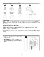
Page 6: ...s Safety Glasses Stepladder and Wire Strippers Helpful Tools not included AC Tester Light Tape Measure Do It Yourself Wiring Handbook and Wire Cutters HARDWARE CONTENTS shown actual size PREPARATION D...

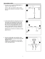
Page 7: ...ove that mounting plate screw I Then remove mounting plate screw I on outer edge of mounting plate A directly opposite the mounting plate screw I that was just removed Partially loosen the other two r...

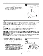
Page 8: ...to determine wiring WARNING Using a full range dimmer switch not included to control fan speed will cause a loud humming noise from fan To reduce the risk of fire or electrical shock do NOT use a full...

Page 9: ...PULL CHAIN LIGHT BY WALL SWITCH 1b BLACK BLUE 120V POWER FROM CEILING BLACK POWER BLACK WALL SWITCH WHITE NEUTRAL GROUND GREEN BARE GREEN CC CC CC CC 1c FAN AND LIGHT CONTROLLED BY TWO WALL SWITCHES C...

Page 10: ...r and partially loosen the other two motor plate screws G Align slotted holes in fitter plate C with loosened motor plate screws G allowing female plug from motor housing B to come through hole in mid...

Page 11: ...WHITE molex wire from fitter plate C Connect BLUE molex wire from LED light kit D to BLACK or BLUE molex wire from fitter plate C Make sure molex wire connections snap together securely 5 C 6 Connect...

Page 12: ...Carefully arrange wires in center of fitter plate C Align slotted holes in edge of LED light kit D with loosened fitter plate screws H on fitter plate C Re insert the other fitter plate screw H previo...

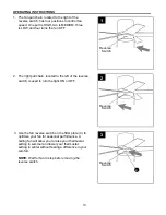
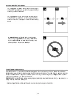
Page 13: ...is HIGH two is MEDIUM three is LOW and four turns the fan OFF 1 2 2 1 Reverse Switch Use the fan reverse switch on the fitter plate C to optimize your fan for seasonal performance A ceiling fan will a...

Page 14: ...a damp cloth to clean the ceiling fan Total wattage for this fixture is 18 watts do not attempt to replace the LEDs CARE AND MAINTENANCE OPERATING INSTRUCTIONS 3a 3b 3c 3c IMPORTANT Reverse switch mus...

Page 15: ...e dimmer switch 4 Fan is new 1 Tighten all blade screws 2 Replace blade 3 Replace with an approved speed control device 4 Allow fan a break in period of a few days especially when running the fan at M...

Page 16: ...ed person will render the warranty invalid Due to varying climatic conditions this warranty does not cover changes in brass finish rusting pitting tarnishing corroding or peeling Brass finish fans mai...

Page 17: ...compra Preguntas problemas piezas faltantes Antes de volver a la tienda llame a nuestro Departamento de Servicio al Cliente al 1 800 527 1292 de lunes a viernes de 8 30 a m a 5 p m ART CULO 2599766 28...

Page 18: ...perjudicial a las comunicaciones de radio Sin embargo no se garantiza que no se producir n interferencias en una instalaci n en especial Si este equipo genera una interferencia perjudicial para la rec...

Page 19: ...ente aseg rese de que est bien sujeta a la estructura del edificio y que pueda sostener el peso del ventilador El incumplimiento de dicho paso podr a provocar lesiones graves o la muerte La estabilida...

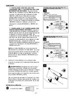
Page 20: ...ue se proporcionan con este ventilador anular la garant a Antes de proceder aseg rese de cortar la alimentaci n el ctrica del interruptor principal o interruptor de circuito a fin de evitar descargas...

Page 21: ...arcasa del motor 1 C Placa de soporte 1 D Kit de iluminaci n LED 1 E Pantalla 1 F Aspa 5 G Tornillo de la placa del 3 motor preensamblado a la carcasa del motor B DESCRIPCI N PIEZA CANTIDAD H Tornillo...

Page 22: ...de seguridad escalera de tijera y pelacables Herramientas tiles no se incluyen luz de prueba de CA cinta m trica manual de cableado h galo usted mismo y pinzas cortacables PREPARACI N INSTALACI N INIC...

Page 23: ...tren al menos a 76 2 cm de distancia de cualquier tipo de obstrucci n y al menos a 2 13 m del piso 2 2 F 76 2 cm m n 2 13 m m n Gancho en forma de J Ubique el tornillo de la placa de montaje I preensa...

Page 24: ...electricista profesional determine el cableado adecuado ADVERTENCIA el uso de un regulador de intensidad de rango completo no se incluye para controlar la velocidad del ventilador provocar un zumbido...

Page 25: ...al ventilador El cable AZUL es el que proporciona alimentaci n al kit de iluminaci n El cable BLANCO es para el ventilador y el kit de iluminaci n El cable VERDE o DESNUDO es la puesta a tierra Cubra...

Page 26: ...F con los orificios del lado inferior del motor Fije el aspa F con los tornillos para aspas AA y con las arandelas para aspas de fibra BB Luego apriete cada uno de los tornillos para aspas AA Comienc...

Page 27: ...e conectados Enchufe macho Enchufe hembra INSTALACI N FINAL Conecte el cable BLANCO del kit de iluminaci n LED D con el cable BLANCO de la placa de soporte C Conecte el cable AZUL del kit de iluminaci...

Page 28: ...illos de la placa de soporte H 7 Alinee las ranuras de la pantalla E con las protuberancias en la parte interior de la placa de soporte C Gire la pantalla E hacia la derecha en direcci n de las maneci...

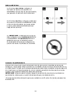
Page 29: ...os para la velocidad MEDIA tres para la velocidad BAJA y cuatro para APAGAR el ventilador 1 2 Interruptor de reversa Interruptor de reversa Utilice el interruptor de reversa de la placa de soporte C p...

Page 30: ...ce agua ni un pa o h medo para limpiar el ventilador de techo El vataje total del kit de iluminaci n para este ventilador es de 18 vatios No intente reemplazar las bombillas LED 3c IMPORTANTE el inter...

Page 31: ...sidad de rango completo 4 El ventilador es nuevo 1 Apriete todos los tornillos de las aspas 2 Reemplace el aspa 3 Use solo el dispositivo de control de velocidad que se incluye 4 Permita que el ventil...

Page 32: ...abado de lat n mantienen su belleza cuando se los protege de las condiciones clim ticas cambiantes La garant a no cubre los elementos de vidrio incluidos con este ventilador Cualquier reemplazo de pie...

Reviews: