background image

D

B

F

M

J

I


IMPORTANT:

 You must use the parts provided 

with this fan for proper installation and safety.

  A 

Downrod  

1

  B 

Canopy 

1

  C 

Mounting Bracket 

1

  D 

Motor Housing 

1

  E 

Star Washer 

4


(preassembled)

  F 

Light Kit Fitter 

1

  G 

Blade  

5

  H 

Blade Arm 

5


Glass Shade 

3


Motor Screw 

10


(preassembled) 

+ 1 extra

DESCRIPTION

PART

QUANTITY

PACKAGE CONTENTS

5

P

DESCRIPTION

PART

QUANTITY

  K 

Lock Washer 

10


(preassembled) 

+ 1 extra


Pin (preassembled) 

1

  M 

Clip (preassembled) 

1

  N 

Bulb 

3

  O 

Canopy Mounting Screw 

4


(preassembled)

  P 

Switch Housing Screw 

3


(preassembled)

H

G

A

L

N

C

O

E

K

Summary of Contents for 1461040

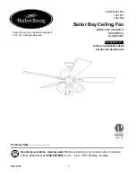
Page 1: ...040 1461041 1461042 Questions problems missing parts Before returning to your retailer call our customer service department at 1 800 643 0067 8 a m 8 p m EST Monday Sunday Purchase Date 1 Espa ol p 21...

Page 2: ...f wiring handbook if you are unfamiliar with installing electrical wiring Make sure the installation site you choose allows a minimum clearance of 7 ft from the blades to the floor and at least 30 in...

Page 3: ...tors to use To reduce the risk of fire or electrical shock do not use the fan with any solid state speed control device or control fan speed with a full range dimmer switch To reduce the risk of fire...

Page 4: ...ommunications However there is no guarantee that interference will not occur in a particular installation If this equipment does cause harmful interference to radio or television reception which can b...

Page 5: ...her 4 preassembled F Light Kit Fitter 1 G Blade 5 H Blade Arm 5 I Glass Shade 3 J Motor Screw 10 preassembled 1 extra DESCRIPTION PART QUANTITY PACKAGE CONTENTS 5 P DESCRIPTION PART QUANTITY K Lock Wa...

Page 6: ...Tools Required for Assembly not included Electrical Tape Phillips Screwdriver Pliers Safety Glasses Stepladder and Wire Strippers Helpful Tools not included AC Tester Light Tape Measure Do It Yourself...

Page 7: ...r ceilings you may want to use a longer downrod not included Angle style mounting is best suited for angled or vaulted ceilings A longer downrod is sometimes necessary to ensure proper blade clearance...

Page 8: ...id confusion during installation For DOWNROD STYLE FAN MOUNTING proceed to Step 1 below For CLOSEMOUNT STYLE FAN MOUNTING skip to page 10 5 J D Plastic Motor Block 1 M D L A Yoke DOWNROD STYLE FAN MOU...

Page 9: ...ot included NOTE If you do not cut back the lead wires Steps 4 and 5 are not necessary and you may proceed to Step 6 instead 4 3 DOWNROD STYLE FAN MOUNTING Slip downrod A into motor housing yoke align...

Page 10: ...T STYLE FAN MOUNTING Remove preassembled canopy cover from bottom of canopy B NOTE To remove canopy cover from canopy B twist canopy cover until the two small protrusions on the inner lip of the canop...

Page 11: ...the mounting bracket C using one of the non slotted holes in the canopy B 4 3 Tab C 4 B Pull wires up through hole in the middle of the canopy B and attach canopy B to motor housing D using the three...

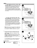
Page 12: ...ire or electrical shock do NOT use a full range dimmer switch to control fan speed WIRING NOTE This fan is remote control adaptable remote control not included Please refer to instructions provided wi...

Page 13: ...e of the outlet box from the BLACK and BLUE wire connections Turn spliced taped wires upward and gently push wires and wire connectors CC into outlet box 2 CC Wire Connector x 4 Hardware Used CC CC 2...

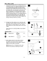
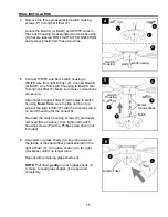
Page 14: ...TE Make sure to completely secure each blade arm H before proceeding to the next 3 3 D J G H J 1 Temporarily lift canopy B to mounting bracket C to determine which two canopy mounting screws O in moun...

Page 15: ...holes in light kit fitter F with holes in switch housing Note Make sure to align notch on top edge of the light kit fitter F with the reverse switch on switch housing for the correct fit Re insert th...

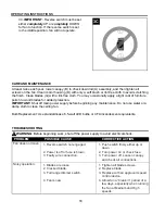
Page 16: ...ONS The fan pull chain located on the switch housing of motor housing D has four positions to control fan speed One pull is HIGH two is MEDIUM three is LOW and four turns the fan OFF 1 8 Attach pull c...

Page 17: ...summer and lower your thermostat setting in winter without feeling a difference in your comfort NOTE Wait for fan to stop before moving the reverse switch 3A In warmer weather setting the reverse swit...

Page 18: ...any maintenance Do not use water or a damp cloth to clean the ceiling fan Bulb Replacement Use standard base 6 5 watt LED bulbs or CFL incandescent equivalents WARNING Before beginning work shut off t...

Page 19: ...ipt as proof of purchase All cost of removal and reinstallation are the express responsibility of the purchaser Any damage to the ceiling fan by accident misuse or improper installation or by using pa...

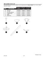
Page 20: ...A Downrod B Canopy C Mounting Bracket F Light Kit Fitter G Blade H Blade Arm 1461040 A 1461040 B 1461040 C 1461040 F 1461040 G 1461040 H PART DESCRIPTION 1461040 PART A B H F G Printed in China C 1461...

Page 21: ...zas faltantes Antes de volver a la tienda llame a nuestro Departamento de Servicio al Cliente al 1 800 643 0067 de lunes a domingo de 8 a m a 8 p m hora est ndar del Este Fecha de compra 21 4007498 Ve...

Page 22: ...cado o consulte un manual de cableado para hacerlo usted mismo Aseg rese de que el sitio de instalaci n que elija permita establecer una distancia m nima de 2 13 m desde las aspas hasta el piso y que...

Page 23: ...ebe utilizar Para reducir el riesgo de incendios o descargas el ctricas no use el ventilador con dispositivos de control de velocidad para ventiladores de estado s lido ni controle la velocidad del ve...

Page 24: ...rencia perjudicial a las comunicaciones de radio Sin embargo no se garantiza que no se producir n interferencias en una instalaci n en especial Si este equipo genera una interferencia perjudicial para...

Page 25: ...ilizar las piezas que se incluyen con este ventilador para la instalaci n adecuada y por seguridad A Varilla 1 B Base 1 C Soporte de montaje 1 D Carcasa del motor 1 E Arandela de estrella 4 preensambl...

Page 26: ...cinta aislante destornillador Phillips pinzas gafas de seguridad escalera de tijera y pinzas pelacables Herramientas tiles no se incluyen luz de prueba CA cinta m trica manual de cableado H galo usted...

Page 27: ...ndamos utilizar una varilla m s larga no se incluye El montaje en ngulo es mejor para los techos en ngulo o de b veda En ocasiones es necesaria una varilla m s larga para asegurar el espacio libre de...

Page 28: ...EL VENTILADOR EN ESTILO DE VARILLA proceda al Paso 1 a continuaci n Para realizar el MONTAJE DEL VENTILADOR EN ESTILO CERRADO siga a la p gina 30 Retire el pasador L y el sujetador M de la varilla A A...

Page 29: ...4 y 5 no son necesarios y puede proceder con el Paso 6 en su lugar 4 3 MONTAJE DEL VENTILADOR EN ESTILO DE VARILLA Deslice la varilla A en la horquilla de la carcasa del motor alinee los orificios y v...

Page 30: ...base de la parte inferior de la base B NOTA para retirar la cubierta de la base gire la cubierta de la base hasta que las dos protuberancias peque as en el borde interior de la cubierta de la base se...

Page 31: ...ntaje C en uno de los orificios sin ranura de la base B 4 3 3 B D Leng eta Pase los cables hacia arriba a trav s del orificio en el centro de la base B y fije la base B a la carcasa del motor D con lo...

Page 32: ...ntilador Para reducir el riesgo de incendios o descargas el ctricas NO use un regulador de intensidad de rango completo para controlar la velocidad del ventilador NOTA este ventilador puede adaptarse...

Page 33: ...AZUL es el que proporciona alimentaci n al kit de iluminaci n El cable BLANCO es para el ventilador y el kit de iluminaci n El cable VERDE o DESNUDO es la puesta a tierra Cubra con cinta aislante no s...

Page 34: ...to con las arandelas de estrella E que acaba de retirar y apriete todos los tornillos de montaje de la base O firmemente 2 Inserte parcialmente tres tornillos para aspa AA junto con tres arandelas par...

Page 35: ...rcasa del interruptor Nota aseg rese de alinear la muesca en el extremo superior del soporte del kit de iluminaci n F con el interruptor de reversa de la carcasa del interruptor para que calce correct...

Page 36: ...motor D tiene cuatro posiciones para controlar la velocidad del ventilador Un movimiento activa la velocidad ALTA dos para la velocidad MEDIA tres para la velocidad BAJA y cuatro para APAGAR el ventil...

Page 37: ...no y disminuirla en invierno sin sentir una diferencia en su comodidad NOTA espere a que el ventilador se detenga antes de mover el interruptor de reversa 3A En climas m s c lidos la configuraci n del...

Page 38: ...emplazo de las bombillas use bombillas de LED de base est ndar de 6 5 vatios o bombillas CFL incandescentes equivalentes ADVERTENCIA antes de comenzar cualquier trabajo desconecte el suministro de ele...

Page 39: ...de techo por un modelo comparable o superior Para obtener el servicio de garant a presente una copia del recibo de venta como comprobante de la compra Todos los costos de extracci n y reinstalaci n s...

Page 40: ...ndar del Este A Varilla B Base C Soporte de montaje F Soporte del kit de iluminaci n G Aspa H Brazo del aspa 1461040 A 1461040 B 1461040 C 1461040 F 1461040 G 1461040 H PIEZA DESCRIPCI N 1461040 PIEZA...

Reviews: