background image

1

2

3

G

G

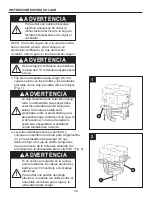
3. Fije firmemente el conector de 4 clavijas y el 
    de 2 clavijas de señal del ensamble del motor 
    (A) al ensamble de la placa del portalámpara 
    (H). (Fig. 3)               
       

A

A

G

H

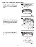
INSTALACIÓN DEL ENSAMBLE DE LA PLACA DE ILUMINACIÓN

1. Fije firmemente el conector de 9 clavijas del 
    ensamble del motor (A) al portalámparas con 
    arnés de cableado que se encuentra dentro 
    del ensamble de la placa de iluminación (G). 
    (Fig. 1)      

2. Retire uno de los tres tornillos de la 
    abrazadera de soporte en el ensamble del 
    motor (A). Afloje ligermente los dos tornillos  
    restantes. Coloque el ensamble de la placa de 
    iluminación (G) en el ensamble del motor (A) 
    usando los dos chaveteros. Vuelva a colocar 
    el tercer tornillo y apriete todos los tornillos. 
    (Fig. 2)    

34

Summary of Contents for 0356999

Page 1: ...T HERE Serial Number Purchase Date Harbor Breeze is a registered trademark of LF LLC All Rights Reserved Questions problems missing parts Before returning to your retailer call our customer service department at 1 800 643 0067 8 a m 6 p m EST Monday Thursday and 8 a m 5 p m EST Friday ...

Page 2: ... Hanging Instructions Wiring Instructions Canopy Housing Installation Blade Installation Light Plate Assembly Installation Pull Chain Operating Instructions Blade Balancing Installation Instructions Care and Maintenance Troubleshooting Warranty Replacement Parts List 3 5 6 6 7 9 10 11 12 13 15 17 18 18 20 21 ...

Page 3: ...ing conductor Do not install or use fan if any part is damaged or missing WARNING Read all instructions and safety information before installing your new fan Review accompanying assembly diagrams CAUTION To reduce the risk of fire electrical shock or personal injury wire connectors provided with this fan are designed to accept only one 12 gauge house wire and two lead wires from the fan If your ho...

Page 4: ...4 SAFETY INFORMATION Continued The net weight of this fan is 26 46 lbs 12 kg This fan is to be used in dry locations only WARNING ...

Page 5: ...5 A B C F I G H J K L M D E PART DESCRIPTION QUANTITY A Motor Assembly 1 B Hanger Bracket 1 C Downrod Hanger Ball 1 Assembly D Ceiling Canopy 1 E Canopy Screw Cover 1 F Motor Coupling Cover 1 G Light Plate Assembly 1 H Socket Plate Assembly 1 I Glass 1 J Blade Holder Arm 5 Bulb 5 5 ...

Page 6: ...mated Assembly Time 60 minutes Tools Required for Assembly not included Phillips screwdriver 1 4 in flathead screwdriver wire stripper and step ladder Helpful Tools not included AC tester light do it yourself wiring handbook and wire cutters PREPARATION HARDWARE CONTENTS shown actual size Screws Qty 11 AA Wire Connectors Qty 4 CC DD Fan Chain Coupler Qty 1 Balance Kit not shown to size Qty 1 FF EE...

Page 7: ...C Fig 2 1 2 WARNING It is critical that the clevis pin in the downrod support is properly installed and the set screws and nuts are securely tightened Failure to do so could result in the fan falling 3 C A 3 Thread the downrod of the downrod hanger ball assembly C into the downrod support on top of the motor assembly A Install the clevis pin from the downrod hanger ball assembly C by aligning the ...

Page 8: ...od hanger ball assembly C through the two holes in the downrod and align the hanger ball so the pin is captured in the groove in the top of the hanger ball Pull the hanger ball up tight against the pin Securely tighten the set screw in the hanger ball Fig 5 CAUTION A loose set screw could result in a wobbly fan 6 Cut off excess lead wire approximately 6 to 9 in above top of the top of the downrod ...

Page 9: ... remove wallboard until bracket contacts box If bracket and or outlet box are not securely attached the fan could wobble or fall WARNING Failure to seat tab in groove could cause damage to electrical wires and possible shock or fire hazard To avoid possible shock do not pinch wires between the hanger ball assembly and the hanger bracket 1 Securely attach the hanger bracket B to the outlet box usin...

Page 10: ...advice as it must be grounded for safe operation Hardware Used CC x 3 Wire Connectors 1 Connect the green grounding lead from the downrod hanger ball assembly C and the green grounding lead from the hanger bracket B to the supply grounding conductor this may be a bare wire or wire with green colored insulation Securely connect wires with wire connectors CC Securely connect the white fan motor wire...

Page 11: ...crews in the hanger bracket B Loosen the second shoulder screw without fully removing it Assemble ceiling canopy D by rotating key slot over shoulder screw in hanger bracket B Tighten shoulder screw Fully assemble and tighten second shoulder screw that was previously removed Fig 1 2 Securely attach and tighten the canopy screw cover E over the shoulder screws in the hanger bracket B utilizing the ...

Page 12: ...flat surface with the inside of the blade holder medallion K facing up This is the side with the threaded posts and pitched foot Position the blade M over the blade holder medallion K with the threaded posts showing Make sure the bottom edge of the blade M is fully seated against the blade holder medallion K Place blade holder arm J on top of the blade holder cover M positioning the holes over the...

Page 13: ...4 pin and 2 signal pin connector from the motor assembly A to the socket plate assembly H Fig 3 2 Remove one of the three screws in the support bracket on motor assembly A Slightly loosen the remaining two screws Assemble the light plate assembly G to the motor assembly A using the two key slots in the adapter assembly Replace the third screw and securely tighten all three screws Fig 2 A A G H 13 ...

Page 14: ...hten all three screws Fig 4 5 Install bulb L Fig 5 6 Securely attach glass I by twisting clockwise onto the light plate assembly G Don t overtighten or force it Fig 6 CAUTION Bulb is pressurized and may shatter DO NOT TOUCH BULB WITH BARE HANDS Fingerprints may result in shorter bulb life Remove fingerprints with alcohol prior to use To reduce the risk of fire use 100 watt max type T4 minican JD E...

Page 15: ...ull Chain Operating Sequence 3 DD DD EE PULL CHAIN OPERATING INSTRUCTIONS 1 1 Restore electrical power to the outlet box by turning the electricity on at the main fuse box Fig 1 ON ON ON ON ON ON ON ON 2 2 Install the fan chain coupler DD and light kit chain coupler EE Fig 2 Hardware Used DD Fan Chain Coupler EE Light Kit Chain Coupler x 1 x 1 15 ...

Page 16: ... Operating Sequence 5 5 If airflow is desired in the opposite direction turn the fan off and wait for the blades to stop turning Take off the glass I and slide the reverse switch to the opposite position and reinstall the glass I to fan and turn fan on again Fig 5 Season Summer Winter Rotation Direction Switch Position Clockwise Counterclockwise Left Right Reverse Switch Information 16 ...

Page 17: ... FF to the top edge of the blade M near the blade holder arm of the motor assembly A Fig 2 Start the fan and notice wobble Stop the fan and move the balancing clip in the balance kit FF in small steps toward the end of the blade M At each incremental step turn on the fan and observe the wobble Determine the location of the balancing clip in the balance kit FF that gives the least amount of wobble ...

Page 18: ...ews securing fan blade holders to motor hub are loose 1 Attach blades to fan before operating 2 Check to make sure all screws in motor housing are snug do not overtighten screws which 3 Check to make sure the attach the fan blade holders to the motor hub are tight PROBLEM POSSIBLE CAUSE CORRECTIVE ACTION Do not install or use fan if any part is damaged or missing WARNING WARNING Make sure main pow...

Page 19: ...ht and result in a smoother operation For example exchange blades in positions 1 and 3 or 1 and 4 If this does not improve wobble exchange 2 and 4 or 2 and 5 1 If possible consider using a longer downrod For example use a 12 in downrod instead of a 4 5 in downrod that comes with your fan Tighten both set screws and nuts securely in downrod support 2 Tighten the set screw in the downrod hanger ball...

Page 20: ...tarnishing corroding or peeling Brass finish fans maintain their beauty when protected from varying weather conditions Any glass provided with this fan is not covered by the warranty Any replacement of defective parts for the ceiling fan must be reported within the first year from the date of purchase For the balance of the warranty call our customer service department at 1 800 643 0067 for return...

Page 21: ...01LAZ LBALKT Motor Assembly Hanger Bracket Downrod Hanger Ball Assembly Ceiling Canopy Canopy Screw Cover Motor Coupling Cover Light Plate Assembly Socket Plate Assembly Glass Blade Holder Arm Blade Holder Medallion Bulb Blade Screw Pan Head Screw Wire Connector Fan Chain Coupler Light Kit Chain Coupler Balancing Kit A B C D E F G H I J K L M AA BB CC DD EE FF For replacement parts call our custom...

Page 22: ...Z VENTILADOR DE TECHO HIGHLANDER Adjunte su recibo AQUÍ Número de serie Fecha de compra Preguntas problemas piezas faltantes Antes de volver a la tienda llame a nuestro Departamento de Servicio al Cliente al 1 800 643 0067 de lunes a jueves de 8 a m a 6 p m y los viernes de 8 a m a 5 p m hora estándar del Este ...

Page 23: ...nstrucciones para colgar Instrucciones de cableado Instalación de la carcasa de la base Instalación de las aspas Instalación del ensamble de la placa de iluminación Instrucciones de funcionamiento de la cadena del tirador Instrucciones de instalación de aspa equilibrada Cuidado y mantenimiento Solución de problemas Garantía Lista de piezas de repuesto 23 ...

Page 24: ... deben usar PRECAUCIÓN ADVERTENCIA Asegúrese de que todas las conexiones eléctricas cumplan con los códigos locales las ordenanzas o el Código Nacional de Electricidad Si no está familiarizado con la instalación del cableado eléctrico contrate a un electricista calificado o consulte un manual de cableado para hacerlo usted mismo Asegúrese de que el sitio de instalación que elija permita una distan...

Page 25: ...cada como ACCEPTABLE FOR FAN SUPPORT APTA PARA SOPORTE DE VENTILADOR y use los tornillos de montaje que se proporcionan con la caja de salida La mayoría de las cajas de salida que se usan comúnmente para sostener ensambles de iluminación no son aptas para sostener un ventilador y puede ser necesario reem plazarlas Si tiene dudas consulte con un electricista calificado El peso neto de este ventilad...

Page 26: ...te del aspa Medallón del soporte del aspa Bombilla Aspa C A B D E F PIEZA DESCRIPCIÓN CANTIDAD 1 1 1 5 1 1 1 1 1 1 H I J K L M G Ensamble del motor Abrazadera para colgar Escudo del techo Ensamble de la bola para colgar varilla Cubierta para los tornillos de la base Cubierta para el acoplador del motor Ensamble de la placa de iluminación 26 ...

Page 27: ...to Tiempo estimado de ensamblaje 60 minutos Herramientas necesarias para el ensamblaje no se incluyen Destornillador Phillips destornillador de punta plana de 1 4 pinzas pelacables y escalera de tijera Herramientas útiles Luz de prueba CA manual de cableado para hacerlo usted mismo y pinzas cortacables PREPARACIÓN ADITAMENTOS Se muestra en tamaño real FF Kit de equilibrio no se muestra en tamaño r...

Page 28: ... Haga pasar la varilla del ensamble de la bola para colgar varilla C por el soporte para varilla en la parte superior del ensamble de motor A Instale el pasador de horquilla del ensamble de la bola para colgar varilla C alineando los orificios del ensamble de soporte de la varilla A con los orificios del ensamble de la bola para colgar varilla C Fije el pasador de horquilla con el sujetador de hor...

Page 29: ... través de los dos orificios de la varilla y alinee la bola para colgar de manera tal que el pasador quede inserto en la ranura de la parte superior de la bola para colgar Sujete la bola para colgar firmemente al pasador Fije bien el tornillo de fijación a la bola para colgar Fig 5 Un tornillo de fijación flojo podría hacer que el ventilador se tambalee PRECAUCIÓN 6 Corte el excedente del cable co...

Page 30: ... bien asegu rada La abrazadera para colgar debe estar bien asentada contra la caja de salida Si la caja de salida está empotrada retire el panel hasta que la abrazadera haga contacto con la caja Si la abrazadera y o la caja de salida no están bien aseguradas el ventilador podría tambalearse o caerse ADVERTENCIA 2 Levante cuidadosamente el ventilador y coloque el ensamble de la bola para colgar var...

Page 31: ...e cortar la alimentación eléctrica de la caja de fusibles principal antes de colgar el ventilador ADVERTENCIA NOTA Si no está seguro de si la caja de salida tiene conexión a tierra pida consejo a un electri cista certificado ya que debe tener conexión a tierra para un funcionamiento seguro 1 CC CC Conductor verde puesta a tierra Conductor blanco del suministro Conductor blanco del ventilador Condu...

Page 32: ...tornillo de reborde Ensamble por completo el segundo tornillo de reborde que antes había retirado y apriételo Fig 1 Para evitar una posible descarga eléctrica o incendio asegúrese de colocar los cables eléctricos completamente dentro de la carcasa de la base y de no apretarlos entre la carcasa y el techo ADVERTENCIA 2 Coloque y ajuste firmemente la cubierta para el tornillo de la base E sobre los ...

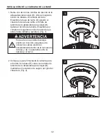
Page 33: ...K Coloque el brazo de soporte del aspa J sobre el soporte de aspas K y alinee los orificios sobre los pilotes roscados Apriete los tornillos con cabeza de arandela BB para asegurar el aspa M y el brazo del soporte del aspa J a la cubierta del soporte del aspa K Fig 1 AA NOTA Periódicamente verifique los aditamentos de los soportes de las aspas y vuelva a asegurarlos si es necesario 2 Fije los sopo...

Page 34: ...avijas del ensamble del motor A al portalámparas con arnés de cableado que se encuentra dentro del ensamble de la placa de iluminación G Fig 1 2 Retire uno de los tres tornillos de la abrazadera de soporte en el ensamble del motor A Afloje ligermente los dos tornillos restantes Coloque el ensamble de la placa de iluminación G en el ensamble del motor A usando los dos chaveteros Vuelva a colocar el...

Page 35: ...mbilla L Fig 5 La bombilla está presurizada y puede quebrarse NO TOQUE LA BOMBILLA CON LAS MANOS DESPROTEGIDAS Las huellas dactilares en la bombilla pueden reducir la vida útil de la misma Elimine las huellas dactilares con alcohol antes de usar la bombilla Para disminuir el riesgo de incendios utilice una bombilla minican tipo T4 JD E11 de tungsteno halógena de 100 vatios como máximo Apague el in...

Page 36: ...dos DD EE x 1 x 1 Acoplador de la cadena del ventilador Acoplador de la cadena del kit de iluminación 2 Instale el acoplador de la cadena del ventilador DD y el acoplador de la cadena del kit de iluminación EE Fig 2 3 Verifique el funcionamiento del ventilador jalando suavemente del acoplador de la cadena del ventilador DD Fig 3 1 ª tirada 2 ª tirada 3 ª tirada 4 ª tirada Alta Apagado Baja Media S...

Page 37: ...sea que el flujo de aire corra en la dirección opuesta apague el ventilador y espere hasta que las aspas dejen de girar Retire el vidrio I y deslice el interruptor de reversa a la posición opuesta y vuelva a instalar el vidrio I en el ventilador y vuelva a encender este último Fig 5 Temporada Verano Invierno Dirección de rotación Posición del interruptor En dirección de las manecillasdel reloj En ...

Page 38: ... el ventilador y mueva el sujetador de equilibrio del kit de equilibrio FF a tramos pequeños hacia el extremo del aspa M En cada tramo de incremento encienda el ventilador y observe el tambaleo Determine la ubicación del sujetador de equilibrio del kit de equilibrio FF que permite la menor cantidad de tambaleo 3 Despegue el papel protector de uno de los cuadrados con peso del kit de equilibrio FF ...

Page 39: ...posición del interruptor de reversa esté completamente hacia un lado 3 Los tornillos que sujetan los soportes de las aspas del ventilador al eje del motor están flojos 3 Compruebe que los tornillos que fijan los soportes de las aspas del ventilador al eje del motor estén ajustados 2 Compruebe que todos los tornillos de la carcasa del motor estén ajustados no apriete demasiado CUIDADO Y MANTENIMIEN...

Page 40: ...del motor están flojos 1 Fije bien ambos tornillos de fijación y sus tuercas al soporte de la varilla 2 Apriete el tornillo de fijación en el ensamble de la bola para colgar varilla 3 Compruebe que los tornillos que fijan los soportes de las aspas del ventilador al eje del motor estén ajustados 4 Los soportes de las aspas no están asentados correctamente 5 La abrazadera para colgar y o la caja de ...

Page 41: ...o descascaramiento Los ventiladores con acabado de latón mantienen su belleza cuando se les protege de las cambiantes condiciones atmosféricas La garantía no cubre los elementos de vidrio incluidos con este ventilador El reemplazo de piezas defectuosas para el ventilador de techo debe informarse dentro del primer año a partir de la fecha de compra Para conocer el saldo de la garantía llame a nuest...

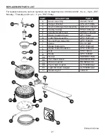
Page 42: ...erta para el acoplador del motor Ensamble de la placa de iluminación Ensamble de la placa del portalámpara Vidrio Brazo de soporte del aspa Medallón de soporte del aspa Bombilla Aspa Tornillos Tornillo de cabeza plana Conectores de cable Acoplador de la cadena del ventilador Acoplador de la cadena del kit de ilunación Kit de equilibrio A B C D E F G H I J K L M AA BB CC DD EE FF LISTA DE PIEZAS DE...

Reviews: