background image

6

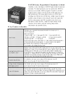
● NP200 Series Programmable Temperature Controller

Versatility is a key advantage of NP200 Programmable Temperature 
Controller. The following features are incorporated into NP200 to 
maximize user benefits. NP200 programs 30 patterns with 300 
segments (each pattern can have maximum 99 segments). The 
high performance CPU allows great accuracy (+/-0.1%) and 
sampling time (100ms). Also, NP200 has multiple inputs (19 types), 
multiple outputs (3 types), auto-tuning (2 types), time signal (5), 
heat & cooling output, level PID calculation and control, and 
emergency output functions. Large back-light display clearly 
indicates unit monitored, program running, elapsed time, 
temperature, and operation mode.

User Output

The User can set a parameter that activates the desired control output up to 10 
 (From U1 through U10).  
User Output includes:  
① Alarm (ALARM 1~4)   ② Time signal (TS1~TS5)    ③ Inner signal (IS1~IS5)
④ Pattern end (PTEND)   ⑤ Program run (RUN)         ⑥ Fixed control mode (FIX)
⑦ Reset mode (RST)      ⑧ Hold (HOLD)                 ⑨ Wait (WAIT)
⑩ Output during the manual control (MAN)   ⑪ Output during the ascending segment 
⑫ Output during the descending segment   ⑬ Output during the soak segment
(Be sure that U10 is assigned to Cooling Operation Output, 
 if a controller is the Heating/Cooling model) 

Heating/Cooling PID Control 
In program control

Heating/Cooling control outputs the PID operational result in two types of signal, that is, for 

heating and for cooling.  You can choose either PID control or ON/OFF control for  the output 

of heating side and cooling side. If you set the proportional value(P) of heating side as 〞

0〟 the ON/OFF control is selected for the heating side, while the fixing of the band(Pc) of 

cooling side 〞0〟 chooses the ON/OFF control for cooling side. . Moreover, you can choose 

one method among heating side output, cooling side output, relay output, voltage pulse 

output and current output and apply the controling function with it.

Universal Input/Output

his controller has two types of auto-tuning as STD(standard type) and LOW 
(Low PV type is the value 10% lower than the set value)


2 Type of Auto Tuning Mode 
(Standard/Low PV)

This controller has two types of auto-tuning as STD(standard type) and LOW 
(Low PV type is the value 10% lower than the set value) 

Level PID Operation


The input range is divided into four levels and differnt PID group is applied to each level.            
If you choose Level function, the PID group is automatically selected by Level irrespective of PID 
number or Set Value Number(SVNO). You can apply different PID data to different range to get 
an optimum PID value in wide temperatare range.

● Key Features & Benefits 

Summary of Contents for NP200

Page 1: ...User Manual NP200 PROGRAMMABLE TEMPERATURE CONTROLLER This user manual intended for use with NP200 VER 010 or newer controllers Please check your model number...

Page 2: ......

Page 3: ...tions 6 3 LCD Displays 7 Menu Display 8 Setting Guideline 8 1 Program Menu 8 2 Operation Menu 8 3 Function Menu FUNC 8 4 Setup Menu 9 Initial Setting Description 9 1 Menu Display 9 2 Setting Example 1...

Page 4: ...possible thermal accumulation due to direct sunlight or heat radiation 11 Install this product at place no higher than 2 000m in altitude 12 Attach the bractets 2pcs on the holes of the panel and tigh...

Page 5: ...ally Min 100 thousand times rated load SSR drive pulse voltage 4 20 mA DC are not insulated with internal circuit 24 The instrument has IP65 protection grade But to guarantee its grade and specificati...

Page 6: ...is the Heating Cooling model Heating Cooling PID Control In program control Heating Cooling control outputs the PID operational result in two types of signal that is for heating and for cooling You c...

Page 7: ...mable Controller 96 X 96 mm Control Type 0 Universal Type 1 Heating Cooling Type Option 0 None 1 RS422 485 Communication Function 2 DI 4 Points External Signal Input 3 RS422 485 Communication Function...

Page 8: ...ect Voltage V 1 5 V 1 5 V Range of Scalling SL L SL H 2000 14000 When using current input use a resistor 250 0 1 on input terminal between No 19 and 20 to convert 4 20mV 0 10 V 0 10 V Direct Voltage m...

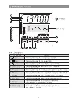
Page 9: ...ture control program running Program run RST Lamp This display lights when the controller operation has been paused through RESET FIX Lamp This display lights when the controller operation is controll...

Page 10: ...mode and end all programs Pressing REST key after a program runs will reset the controller RESET mode and end all FIXs FIX Used to change Operation mode to FIX mode Pressing FIX key after a program r...

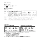
Page 11: ...otal SEG TIME This display indicates the remaining time of running segment hr Min h or Min Sec m REPEAT This display indicates the number s of repeated and total number of repeats Now Repeat Total Rep...

Page 12: ...ing model 2 Auto Mode Heating Cooling model 3 Manual Mode Heating model 4 Manual Mode Heating Cooling model SV This display indicates the minimum value of setting range This display indicates the curr...

Page 13: ...that is not currently being displayed right left both 8 Vertical bar indicates END SEG Graph Display 1 User Output display indicates programmed parameters from 1 through 10 2 The current User Output...

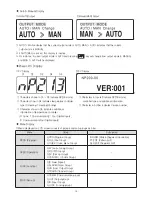
Page 14: ...ler type 0 Heating 1 Heating Cooling Character show in D5 indicates additional information of temperature controller 0 none 1 Communication 2 Four Digital Inputs 3 Communication Four Digital Inputs Ch...

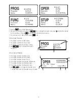
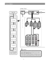
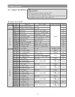
Page 15: ...s This display indicates the Menu name This display indicates the Group name This display indicates the full name of Menu Use key to change the required sub group This display indicates the Menu name...

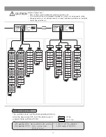
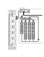
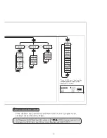
Page 16: ...4 Dc 1 DB 2 DB 3 DB 4 DB 1 LVL 2 LVL LVLD b a c k s i d e 5th operation screen would not be displayed when LOCK A M 0 SV screen OUT screen GRAPH screen USER OUT screen AUTO MAN Power ON 3 s 7 Menu Dis...

Page 17: ...ng Screen Menu setting is recommended after program operation is off It is to prevent setting value changed according to a certain set up parameter setting Some parameter may not indicated due to its...

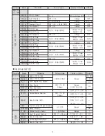
Page 18: ...ON 99 TS2 ON 1 TS3 ON 2 TS3 ON 99 TS3 ON 1 TS4 ON 2 TS4 ON 99 TS4 ON 1 TS5 ON 2 TS5 ON 99 TS5 ON 1 TS1 OFF 2 TS1 OFF 99 TS1 OFF 1 TS2 OFF 2 TS2 OFF 99 TS2 OFF 1 TS3 OFF 2 TS3 OFF 99 TS3 OFF 1 TS4 OFF...

Page 19: ...tern PT n COPY D DELETE F INIT 1 Starts operation from operation mode before Power off But in program mode operation will be followed by ST MD If you ON USE menu display will be changed as below Group...

Page 20: ...End Mode RESET HOLD FIX LINK RESET END TM End Signal Time OFF 0 01 99 59 TIME OFF LINK PT Link Pattern 1 30 END MD LINK 1 01 PID 01 PID NO Select 1 4 Always 1 01 ALM 01 ALM NO Select OFF 1 15 Always...

Page 21: ...SULT Result of File CMD DELETE 1 99 Classification Signal Parameter Set up range Display Condition Default SEG NO 2 98 99 PID PID NO Select 1 4 PID control level OFF 1 99 ALM ALM NO Select OFF 1 15 Al...

Page 22: ...ing Range Display Condition Default Value ARW Anti Reset Wind up AUTO 50 0 200 0 PID Control 50 0 ALPHA Alpha 0 100 PID Control 50 PIDSL PID Group Select 0 4 Set 1 4 to move to next parameter PID Cont...

Page 23: ...ignal 1 OFF ON OFF IS1H Inner Signal 1 High IS1L 1digit EU 100 IS1 ON EU 100 IS1L Inner Signal 1 Low EU 0 IS1H 1digit EU 0 IS2 IS2 Inner Signal 2 OFF ON Always OFF IS2H Inner Signal 2 High IS2L 1digit...

Page 24: ...ge Display Condition Default Value UO1 User Output 1 OFF SGAL Alarm ALM1 ALM4 Time Signal TS1 TS5 Inner Signal IS1 IS5 PTEND PROG FIX RST HOLD WAIT MAN UP DOWN SOAK Always 0FF UO2 User Output 2 UO3 Us...

Page 25: ...sal Relay Heating Cooling SSR SSR O ACT Output Action REVERSE DIRECT Universal REVERSE HCT Heat cycle Time 1 1000 s RLY or SSR Output Except ON OFF control RLY 30 s SSR 2 s CCT Cool cycle Time 1 1000...

Page 26: ...V V 100 0 SL L Scale Limit Low 0 0 RJC RJC ON OFF ON OFF Thermocouple input ON FILT PV Input Filter OFF 1 120 Always OFF BIAS PV Input Bias EUS 100 100 Always EUS 0 B OUT Burn out Select OFF UP DOWN A...

Page 27: ...ger Program Menu Group Program Group Wait Zone Number of Repeat s Time Signal Mode Start Set Value Segment value of each Pattern Time Signal File Group Number of Segment s of each Pattern Pattern Edit...

Page 28: ...00 push key and select INP PT100 and push SET key Each time you push SET key to move the next parameter Select input unit Input Unit select C Setup Full Range High Full Range High FR H 1370 0 C Setup...

Page 29: ...ey Push key to select it Set Wait Time Wait Time WTM OFF display Set WTM 00h 30m by and key Push key to select it Set Repeat Repeat Set REPEAT 1 display Push key to select it Set Time Signal Mode Time...

Page 30: ...S2 OFF Time Signal 2 OFF Time 01h 30m TS3 Time Signal 3 OFF OFF ON Always TS3 ON Time Signal 3 ON Time 00h 00m TS MD Time 1 TS3 ON TS3 OFF Time Signal 3 OFF Time 01h 00m TS4 Time Signal 4 ON ON OFF Al...

Page 31: ...ent number 1 of pattern number 1 Alarm Model Setting Push Key at least 3 seconds from Operation display PROG Push key FUNC Push key and go G ALARM Push key AL MD ALL Push key and select amount ALL FIX...

Page 32: ...elow Alarm Code Default Value Setting Range Default Value Alarm Mode AL MD ALL ALL FIX PROG FIX PROG ALL ALM1 A1TY 1 OFF 1 20 1 A1DB 20 0 EUS 0 100 7 9 AL 1 250 0 PV EU 100 100 PV EUS 100 100 1370 0 A...

Page 33: ...r Signal 1 High Limit Setting Inner Signal 1High IS1H 1370 0 c display Push key and set IS1H 100 0 C Push key to select it Inner Signal 1 Low Limit Setting Inner Signal 1 Low IS1L 200 0 C display Push...

Page 34: ...Down Output Down 13 Pattern Soak Output SOAK UO 2 Use output 2 Time Signal Output 2 TS2 UO 3 Use output 3 Time Signal Output 3 TS3 UO 4 Use output 4 Time Signal Output 4 TS4 UO 5 Use output 5 Time Si...

Page 35: ...ID Group Number PIDNO Set Value SV Time TM Time Signal TS TS ON and TS OFF If PV fails to enter into WZ the Wait function will infinitely repeat To avoid this problem WTM Wait Time needs to be set The...

Page 36: ...ime for Time Signal Output from corresponding segment Time setting mode Setting ON and OFF time separately for Time Signal Output from corresponding segment Also when segment number 0 SEG NO 0 from G...

Page 37: ...l 1 TS1 is 0 Thus TS is activated ON at the beginning of the Segment 1 and deactivated after 1 hour of OFF TM which is same to Segment Time at the end of the Segment 1 Again Time Signal is activated O...

Page 38: ...inning of the first soak segment 2 If PV is in d The program will start at the Segment 1 D PV SV In this case the time designated from E to D in Segment 1 is ignored and the program will run for the t...

Page 39: ...run for the time designated from B to A Starting PV at Program Activation Program Start Point If PV is in c The time designated from E to C is ignored and the program will run for the time designated...

Page 40: ...the End Pattern Time Signal does not occur Pattern End Mode END MD consists of Reset RST Hold HOLD Fixed Control FIX and Link LINK If LINK is selected the pattern number will be displayed on LINK PT...

Page 41: ...NO 1 99 PID Group Number Target Run Time and Time Signal TS TS ON and TS OFF NP200 programs four PID groups Default is PID GROUP 1 All PID control outputs are user programmable and each segment can b...

Page 42: ...the running program stop move to the next segment Pressing RESET key for one second will turn off HOLD and the running program will end While in HOLD the current value of SV is not changed and the con...

Page 43: ...lly Parameters of the newly added segment are default Insert segment parameter has default value Result of File CMD To verify the result of segment add Delete Segment Number To input the segment numbe...

Page 44: ...l TS is being paused during the WAIT as shown in Fig 1 2 below In PV START mode Time Signal TS time is deemed passed as much as the program runs Ex 2 As shown in Fig 1 3 below if ST MD is set to PV PV...

Page 45: ...T mode If the Output Mode is AUTO the Preset Out PO is automatically activated Burn Out The Burn Out does not affect Operation Mode However if the Output Mode is AUTO the Preset Out PO is automaticall...

Page 46: ...3 SV is 20 AT is performed in Segment 3 and the gain value is assigned in relevant PID GROUP 3 Standard Auto Tuning Low PV Auto Tuning SetValue Maximumscale10 ON OFF operation PID Control Time AT ON O...

Page 47: ...use the auto tune calculated PID values Values changed after Auto Tuning will remain unchanged until AT runs again 5 Abnormal Shutdown of the Auto Tuning process If the forced AT shutdown occurs the...

Page 48: ...tiplying by the Cycle Time based on a percentage of its full scale default is 100 User can select the output mode Relay Output Voltage Pulse Output The control is better as the Cycle Time is shorter F...

Page 49: ...ting Cooling Output can be controlled by Key or Communication The Manual Control Output is to control the PID Control Output before the Heating Cooling output calculation Although the Cooling PID calc...

Page 50: ...elected regardless of SVNO or PIDNO The ideal PID control value may vary depending on a range of temperature control The LEVEL function assigns each PID data to each range for efficiency and productiv...

Page 51: ...ID1 3 is selected within a range of SP RDV PV SP RDV If SP RDV PV or SP RDV PV PID 4 is selected PID2 is selected within a range of 1 LVL 2 LVL PID1 is selected within a range of FR L 1 LVL RDV RDV SP...

Page 52: ...d ON DI ON Pattern number can be changed by DI 4 7 Only if DI is valid If DI parameter of Group Control is turned OFF DI OFF DI 4 7 is invalid and the pattern number can be changed by either Key or Co...

Page 53: ...G IS 10 3 Function Menu FUNC NP200 programs five Inner Signal Groups The Inner Signal is effective in FIX Mode and PROG Mode There is no difference between TSV and NSV in FIX Mode Inner Signal Mode IS...

Page 54: ...e 0 65 ON IS2 2SV 50 is not in IS2 Zone 25 35 OFF IS3 2SV 50 is in IS3 Zone 45 55 ON IS4 2SV 50 is not in IS4 Zone 57 60 OFF IS5 IS5 has no value OFF 3 SEG IS1 3SV 70 is not in IS1 Zone 0 65 OFF IS2 3...

Page 55: ...5 35 ON IS3 If the current PV is within the range IS3 45 55 ON IS4 If the current PV is within the range IS4 57 60 ON IS5 Because IS5 is not set OFF OFF Condition IS1 If the current PV is not within t...

Page 56: ...rm Type Figure Alarm Type Figure PV High Limit Alarm Low Deviation Alarm PV Low Limit Alarm High and Low Deviation Alarm High Deviation Alarm High and Low Limit Range Deviation Alarm Alarm Type Code N...

Page 57: ...when the hold mode WAIT User Output activates ON when the wait mode MAN User Output activates ON during the manual control mode PTUP User Output activates ON during the ascending ramp segment PTDOWN...

Page 58: ...SPS Set the parameter to select either Retransmission Output or SPS because both outputs use same terminal Sensor Power Supply Wiring 24 V DC 20 mA Max To prevent personal injury or property damage ca...

Page 59: ...R Used to set the communication address From 1 through 99 Max 31 1 RP T Used to set the communication response time 0 10 Response Time Process Time Response Time X 10ms 0 CAUTION CAUTION PC LINK Commu...

Page 60: ...12 if a controller is the Heating Cooling model The HYS is to set the OUT 0 ON OFF or 4 12 Heating Cooling If OUT is 0 the Hysteresis is for ON OFF operation whereas if OUT is 4 12 the Hysteresis is...

Page 61: ...e from 2 000 through 14 000 regardless of FR H FR L setting range However SL H SL L Changing SL H or SL L setting will initialize EU and EUS parameters Except FR H and FR L Input Group G IN CAUTION Se...

Page 62: ...Example 2 IN 1 5V type FR H FR L SL H SL L RET H RET L DEFAULT DEFAULT change settings change settings FR L 1V 0 0 FR L 1V FR L 1V 3V 50 0 3V FR H 3V FR H 5V 100 0 SL H 100 0 3 2 mA 4 0 mA SL L 50 0 1...

Page 63: ...word locking prevents the accidental or unauthorized change The reference conjunction compensation is automatically performed when the input type is a Thermocouple When the RJC error occurs the error...

Page 64: ...0 Highest value OL H and Lowest value OL L Trial for MAN AT is possible ON OFF hysterisis 0 100 Time resolution the small one in either 0 1 or 10 ms SSR output ON voltage more than 25 V DC Load resis...

Page 65: ...l cycle time 100 ms Retransmission output Retransmission signal PV Process value SV Set value MV Volume of output SPS Power supply for sensor Scaling PV Process value SV Set value Retransmission outpu...

Page 66: ...reverse action in output group Emergency output 0 5 105 0 of output value ON OFF hysteresis 0 0 100 0 of range in case of ON OFF control it is up to hysteresis value in output group Heating cooling h...

Page 67: ...lay process value 5 digit with 7 segment Set value and parameter display LCD Condition display Individual LED NP200 SW1 RUN HOLD LED 1 PROG LED 8 U2 SW2 RESET LED 2 RESET LED 9 U3 SW3 STEP LED 3 FIX L...

Page 68: ...4 1 P AL 3 PRS INP 11 IS4H 1 I AL 4 BPS UNIT 12 IS4L 1 D ALMD PRI FR H 13 ALMSTS IS5 1 MR STP FR L 14 UOSTS IS5H 1 PC DLN DP P 15 DISTS IS5L 1 IC ADR SL H 16 1 DC RPT SL L 17 ERRSTS 1 DB FILT 18 NOWST...

Page 69: ...71 MTM21 MTM71 22 ALM NPT22 MSV22 MSV72 MTM22 MTM72 23 SV NPT23 MSV23 MSV73 MTM23 MTM73 24 TM NPT24 MSV24 MSV74 MTM24 MTM74 25 TS1 NPT25 MSV25 MSV75 MTM25 MTM75 26 TS1ON NPT26 MSV26 MSV76 MTM26 MTM76...

Page 70: ...0008 PIDNO Current PID No 0013 ALMSTS Alarm Status Refer to Bit Map Information 0014 UOSTS User Output Status Refer to Bit Map Information 0015 DISTS DI Status Refer to Bit Map Information 0017 ERRST...

Page 71: ...Cooling dead band X is the symbol that represents the PID number G PID 0318 1 LVL PID Lecel 1 G PID 0328 2 LVL PID Lecel 2 G PID 0348 LVLD Reference DEV G PID 0400 0411 AxTY Alarm Type X is the symbo...

Page 72: ...x Quantity of used segment in each pattern X is the symbol that represents the pattern number 0931 TUSEG Total number of used segments 1001 1099 MSVxx SV per each segment of the running pattern xx is...

Page 73: ...03 0700 0001 0702 0000 0703 0005 CR LF Receiver STX 01DWR OK CR LF 2 Result check execution result Sender STX 01DRR 01 0704 CR LF Receiver STX 01DRR OK 0001 CR LF 3 PT 1 SEG 0 selection Sender STX 01D...

Page 74: ...MA0101E161020 HANYOUNG NUX CO LTD 28 Gilpa ro 71 beon gil Nam gu Incheon Korea Tel 82 32 876 4697 Fax 82 32 876 4696 E mail overseas hynux com www hynux com...

Reviews: