background image

English _

23


!

NETWORK CONNECTION AND SETUP

network connection and setup

You can set up the network settings according to your network configurations.

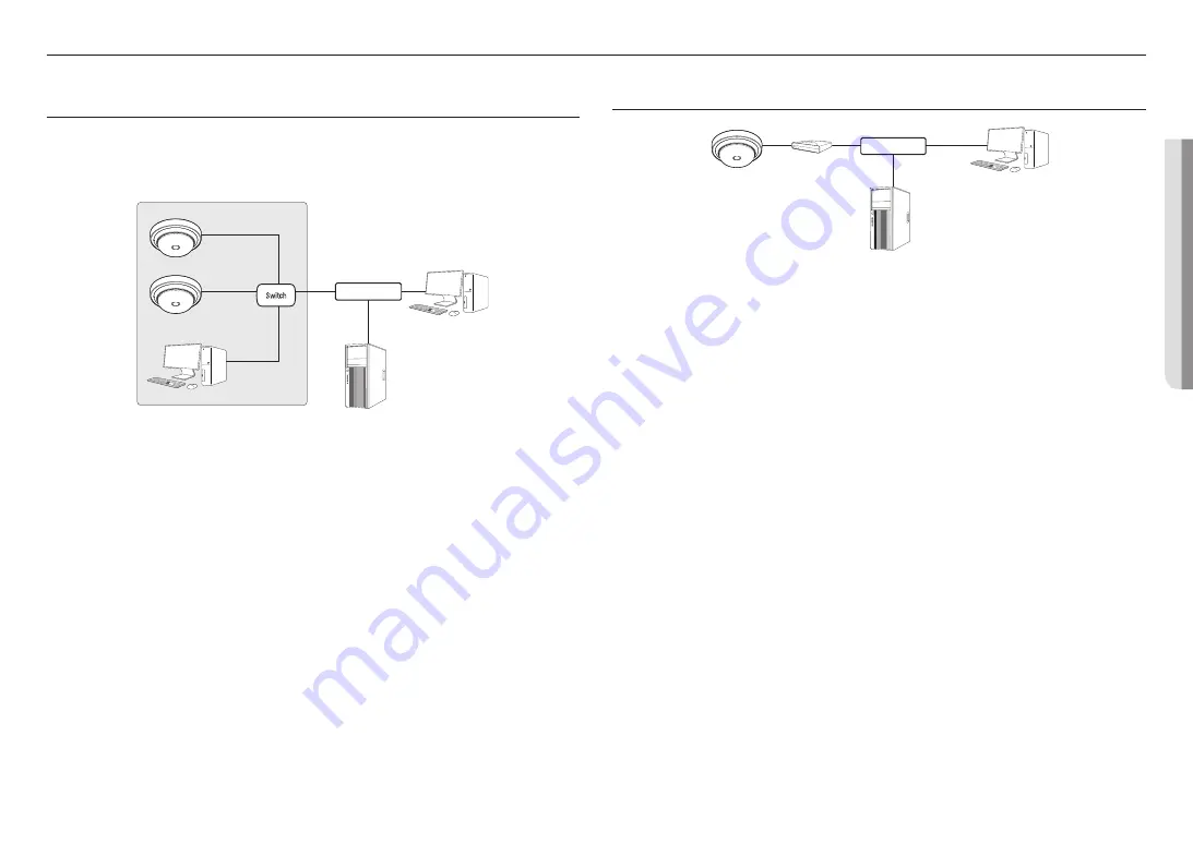
CONNECTING THE CAMERA DIRECTLY TO LOCAL AREA NETWORKING

Connecting to the camera from a local PC in the LAN

1. 

Launch an Internet browser on the local PC.

2. 

Enter the IP address of the camera in the address bar of the browser.

<Local Network>

Camera

Camera

Local PC

INTERNET

External Remote PC

DDNS Server 
(Data Center, KOREA)


M


`

A remote PC in an external Internet out of the LAN network may not be able to connect to the camera installed in the intranet 
if the port-forwarding is not properly set or a firewall is set. 
In this case, to resolve the problem, contact your network administrator.


`

By factory default, the IP address will be assigned from the DHCP server automatically. 
If there is no DHCP server available, the IP address will be set to 192.168.1.100. 
To change the IP address, use the Device Manager. 
For further details on Device Manager use, refer to “

Using Device Manager

”. (Page 24)

CONNECTING THE CAMERA DIRECTLY TO A DHCP BASED DSL/CABLE 
MODEM

Camera

External Remote PC

DDNS Server 
(Data Center, KOREA)

DSL/Cable Modem

INTERNET

1. 

Connect the user PC directly with the network camera.

2. 

Run the Device Manager and change the IP address of the camera so that you can use the web browser 
on your desktop to connect to the camera.

3. 

Use the Internet browser to connect to the web viewer. 

4. 

Move to [

Setup

] page.

5. 

Move to [

Network

] – [

DDNS

] and configure the DDNS settings.

6. 

Move to [

Basic

] – [

IP & Port

], and set the IP type to [

DHCP

].

7. 

Connect the camera, which was removed from your PC, directly to the modem.

8. 

Restart the camera.


M


`

For information on how to set DDNS, refer to the online help of Web Viewer.  


`

For information on how to set the IP format, refer to the online help of Web Viewer.  

Summary of Contents for PNM-C16013RVQ

Page 1: ...NETWORK CAMERA User Manual PNM C16013RVQ...

Page 2: ...correctness of the contents in this document but no formal guarantee shall be provided Use of this document and the subsequent results shall be entirely on the user s own responsibility Hanwha Vision...

Page 3: ...the product in a place where chemical substances or oil mist exists or may be generated As edible oils such as soybean oil may damage or warp the product do not install the product in the kitchen or...

Page 4: ...plant The wired LAN hub providing power over the Ethernet PoE in accordance with IEEE 802 3at shall be a UL Listed device with the output evaluated as a Limited Power Source as defined in UL60950 1 o...

Page 5: ...nd alarm I O NETWORK CONNECTION AND SETUP 23 23 Connecting the Camera Directly to Local Area Networking 23 Connecting the Camera Directly to a DHCP Based DSL Cable Modem 24 Using Device Manager 24 Aut...

Page 6: ...MICRO SD SDHC SDXC MEMORY CARD SPECIFICATIONS Recommended capacity 16 GB 512 GB MLC or 3D TLC type required Recommended Manufacturers SanDisk Transcend Samsung Product Type High endurance Pro enduran...

Page 7: ...tion Camera 1 Top case 1 Quick Guide Optional 1 Cable bushing 1 Extra cable bushing for network cable installation Cap Installer 1 Used to connect the RJ45 cable M Use installation screws of at least...

Page 8: ...In ceiling Mount Wall Mount Base Corner Mount Cabinet Conduit Adaptor SBP 300WMW Wall Mount SBP 300PMW2 required for pole installation SBP 300WMW1 Wall Mount SBP 300PMW2 required for pole installatio...

Page 9: ...apet Mount Assembly Individual Parts SBP 300CMTS Telescopic SBP 300CMTW Telescopic SBP 300CMW1 SBP 900CMW SBP 150CMI SBP 300CMI SBP 180CMS SBP 180CMB SBP 140CMB SBP 150CMP SBP 300CMP SBP 900CMP SBP C1...

Page 10: ...e controlled by the illumination sensor d Reset Button The button restores all camera settings to the factory default Press and hold for about 5 seconds to reboot the system J If you reset the camera...

Page 11: ...English _11 OVERVIEW Components b a Item Description a PoE port This port connects power and network via PoE injector b Micro SD card slot Compartment for the Micro SD card...

Page 12: ...eight of the camera including the installation bracket Stuck in or peeled off cables can cause damage to the product or a fire For safety purposes keep anyone else away from the installation site And...

Page 13: ...the figure J Before installing the camera the Micro SD card should be inserted while the power source and the body are separated Do not forcefully insert it in the reverse direction It might damage yo...

Page 14: ...esired location considering the direction to be monitored mark the locations for the screw holes and cable holes and then drill the holes 1 2 Fix the mount plate using appropriate screws 1 3 Pull out...

Page 15: ...Place the mount plate on the desired location considering the direction to be monitored mark the locations for the screw holes and then drill the holes 2 2 Join the conduit adaptor separately sold to...

Page 16: ...ng the network cable IP66 J Use a cable bushing compliant with the network cable to be connected Camera main use a cable with the diameter of 5 to 6 5 You can only use a network cable with a diameter...

Page 17: ...ust the lens to the desired direction by referring to Adjusting the monitoring direction for the camera If you tilt the lens you may need to adjust the lens as this may block the screen Connect a moni...

Page 18: ...he top case When assembling the top case align the pipe cover part to do so Align the installation groove and push the top case until they click into place Removing the top case Remove the top case by...

Page 19: ...th Adjusting the monitoring direction for the camera Moving the camera module Pan Tilt Lens Rotation Adjusting the monitoring direction You can adjust the camera direction only when the camera is fixe...

Page 20: ...light to radiate evenly when the center of the object is saturated Auto2 Optimized for IR light to evenly radiate at the overall IR brightness Example of installing the ceiling mount Factory default...

Page 21: ...r monitoring purposes Powering and networking Connect the PoE device with the PoE port of the camera J Connect and use a PoE enabled router Use a PoE device that complies with the IEEE 802 3at standar...

Page 22: ...Recommended dongle manufacturer Manufacturer Model NETIS WF2123 n300 EDIMAX EW 7811Un V2 New ver IP Time N100mini IP Time N105L TP LINK TL WN823N V1 TP LINK TL WN725N TP LINK T2U Nano ASUS USB N13 ASU...

Page 23: ...automatically If there is no DHCP server available the IP address will be set to 192 168 1 100 To change the IP address use the Device Manager For further details on Device Manager use refer to Using...

Page 24: ...rator HTTP Port Used to access the camera using the Internet browser defaulted to 80 RTSP Port A port that controls real time streaming The initial value is 554 If using a Broadband Router IP Address...

Page 25: ...K MANUALLY REGISTERING CAMERA If the camera cannot be found using search function the camera can be registered remotely by manually inserting IP information if the camera is connected to external netw...

Page 26: ...t forwarding setting is an example of setting CISCO IP router The settings may differ depending on the connected Broadband Router model For more information refer to the user manual of the applicable...

Page 27: ...NET On a remote computer that is not in the Broadband Router s network cluster is not allowed users can access cameras within a Broadband Router s network by using the camera s DDNS URL 1 Before you c...

Page 28: ...ing system in support of the UPnP protocol 2 Click the camera name for search In the Windows operating system click the camera name searched from the network menu The login window is displayed Connect...

Page 29: ...y using a memo pad or memorizing it LOGIN Whenever you access the camera the login window appears Enter the User ID and password to access the camera 1 Enter admin in the User name input box The admin...

Page 30: ...imized to When adjusting the image alignment for the first time after Factory default initialize it by pressing the RESET button then start adjusting it TROUBLESHOOTING PROBLEM SOLUTION No video is di...

Page 31: ...f where and how they can take these items for environmentally safe recycling Business users should contact their supplier and check the terms and conditions of the purchase contract This product and i...

Page 32: ......

Reviews: