Doc No. IM4772-7
Page 8 of 14
iSense
4
Setting Up the iSense Hardware
4.1
Removing the Front Panel
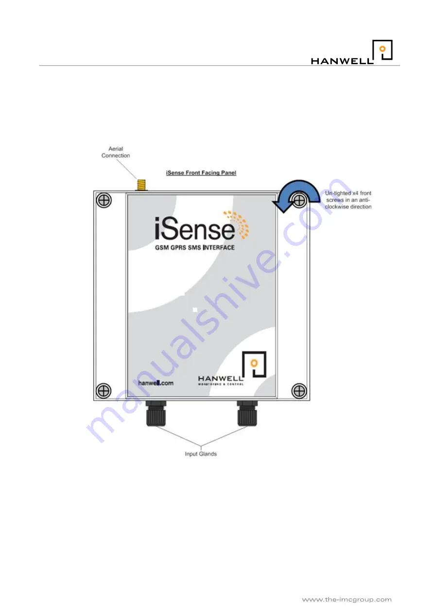
The iSense unit is fastened by four screws that are situated in each corner on the front of the device. By using
a screwdriver to unscrew these four screws the front panel will lift off from the rest of the device. See Figure 1
below for details:
Figure 1 iSense GPRS Unit Front Panel
Once the front panel has been removed the battery pack will be visible on its reverse side. This now leaves
the back panel open and the iSense circuit board accessible.
4.2
Connecting the Aerial
There are two types of aerials which can be attached to this unit, either the extended or the knuckled joint.
Choose one that will better suit the environment that this device will be situated in and simply screw it into the
Aerial connection found on the top of the iSense. The Aerial should be positioned to ensure a good RF signal,
(do not use excessive force tightening the aerial connection, finger tight is adequate).


