background image

TFT-LCD Monitor

5

„

 Controls

   - Front panel

   - Functions

Power button

„

 Power button is located in the lower center of the Front Bezel.

„

 You can push the button to trun on/off the power.

Power Indicating LED

„

 Dark : Power off

„

 Green : Normal mode

„

 Green blinking : DPMS mode or Check Signal Cable mode.

On Screen Display(OSD) Function Button

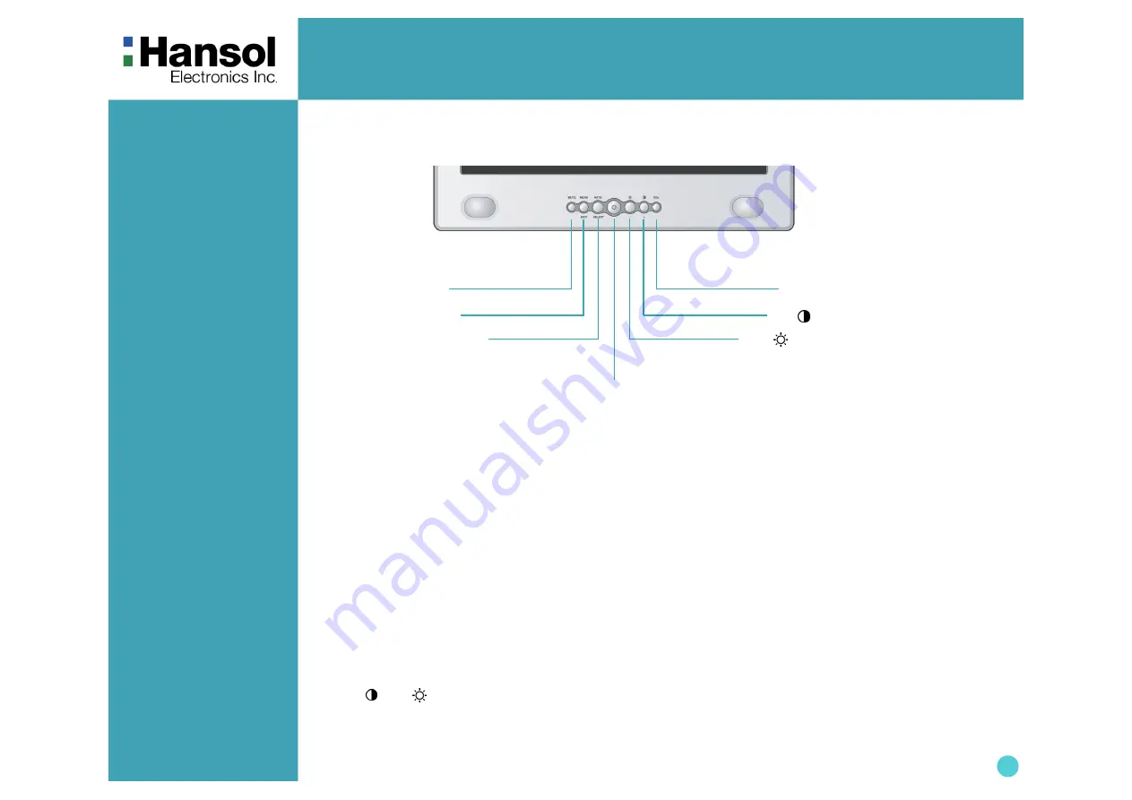
  OSD buttons on the front of bezel perform the following functions.

„

 MUTE : Press this button for mute control.

„

 MENU/EXIT : Press this button to display menus. If you press this button when OSD is displayed, you can switch

                          display to the previous menu and exit menu.

„

 SELECT/AUTO : Press this button, when OSD is not displayed, to perform automatic setting.

                               When OSD is displayed, You can select icons.

„

 POWER : Power button.

„


+

 /      , 

 /     

 : By pressing these button when OSD is displayed, You can move cursor into the menus which


 you want. After press the SELECT button, you can change gauge level or select submenus.  

                            When OSD is not displayed, you can adjust brightness or contrast.

„

 VOLUME : Press this button for volume control.


 /       BUTTON

MENU/EXIT BUTTON

SELECT/AUTO BUTTON

   POWER BUTTON

(Power indicating LED)

+

 /      BUTTON

MUTE BUTTON

VOL BUTTON

Summary of Contents for B15HF

Page 1: ...Package 3 The range of control Angle 3 Connection to Signal Source 4 Controls Front panel 5 Functions 5 Adjusting OSD 6 Power Management Feature 11 Standard Signal Table 11 Specifications 12 Pin assig...

Page 2: ...B digital device pursuant to Part 15 of the FCC Rules These limits are designed to provide reasonable protection against harmful interference in a residential installation This equipment can generate...

Page 3: ...Guide etc Warranty Card Congratulations on your purchase of this top quality color monitor The items illustrated below are contained in the carton First be sure that your carton includes all of them...

Page 4: ...rnal Speaker Port for signal cable from signal source Kensington Lock General For Macintosh Adapter for Macintosh Optional Refer to the table on the rear side of the optional Macintosh adapter and adj...

Page 5: ...display menus If you press this button when OSD is displayed you can switch display to the previous menu and exit menu SELECT AUTO Press this button when OSD is not displayed to perform automatic set...

Page 6: ...ELECT button into the submenu Brightness 1 Use to move Brightness ICON 2 Press SELECT button to select it 3 Use to adjust the brightness Contrast SELECT 1 Use to move Contrast ICON 2 Press SELECT butt...

Page 7: ...move V Position ICON 2 Press SELECT button to select it 3 Use to adjust display upward or downward SELECT 1 Press to move Phase ICON 2 Use SELECT button to select it 3 Use to correct fine trembling o...

Page 8: ...e to select the Mode 1 and Mode 2 2 Press the MENU button to return previous state Mode 1 Reddish white Mode 2 Bluish white User Color SELECT 1 Use to move User color ICON 2 Press SELECT button to sel...

Page 9: ...e OSD V Position ICON 2 Press SELECT button to select it 3 Use to adjust OSD upward or downward OSD Time SELECT 1 Use to move OSD Time ICON 2 Press SELECT button to select it 3 Use to adjust OSD displ...

Page 10: ...ss SELECT button to return to default setting SELECT Information MENU SELECT 1 Use to move the Information ICON 2 Press SELECT button to select it You can know display information Accoding to the char...

Page 11: ...V VGA 720 x 400 31 469 70 087 28 322 VGA 640 x 480 31 469 59 940 25 175 VGA 640 x 480 37 500 75 000 31 500 SVGA 800 x 600 37 900 60 320 40 000 SVGA 800 x 600 46 875 75 000 49 500 XGA 1024 x 768 48 363...

Page 12: ...Synchronization Horizontal Frequency 60 kHz Max Vertical Frequency 75 Hz Max Video Input Video Signal Analog RGB 0 714 Vpp 75 ohm Synchronous Signal Mode H V Separate TTL Sync Power Consumption Maximu...

Page 13: ...ini 15pin connector z 1 5 6 10 11 15 15 Pin D Sub Pin No Assignment 1 Red Video 2 Green Video 3 Blue Video 4 N C 5 Ground 6 Red Video Ground 7 Green Video Ground 8 Blue Video Ground 9 5V Input 10 Grou...

Page 14: ...onfig Adjust clock and PHASE Display is unstable and trembling Check the resolution and frequency of computer and video card and set up again refer to the current monitor mode and standard signal mode...

Reviews: