


HA4AM ELECTRIC MOTOR
COMPENSATED REGULATOR
OPERATION
The regulator pressure setting is altered as the motor
receives a signal from a suitable temperature controller.
The motor responds to maintain the balance in the
electrical circuit. The rotation of the motor is transmitted
through a cam, valve stem, and range spring to the
top of the control module diaphragm. An increase in
temperature decreases the range spring force on top of
the control module diaphragm. This decrease in force on
the diaphragm allows inlet pressure to pass through the
control module to enter the space on top of the piston
which forces the main valve seat open to reduce the
evaporator pressure. A decrease in temperature causes
an increase in the range spring force. This restricts the
flow of inlet pressure to the piston causing a reduction in
the opening of the main valve seat, reducing regulator
flow by raising the pressure setting.
APPLICATIONS
This motor compensated regulator is popular for fruit
storage, precision air temperature control, and liquid
chiller control.
ADJUSTMENT
Adjust the temperature controller as specified by the
manufacturer. Fully open the regulator manually by
turning in (clockwise) the manual-opening stem to cool
the product or room. Once the temperature at the sensing
device is approximately as desired, adjust the controller
output so that the cam is rotated to the center position.
Put regulator back in automatic operation by turning the
manual-opening stem out (counterclockwise). Loosen
the adjustment locking nut. See the diagram to the right.
Turn the adjustment stem clockwise to raise the inlet
pressure setting or counterclockwise to lower the inlet
pressure setting. When the desired refrigerant pressure
setting is achieved, tighten the adjustment locking nut.
A final adjustment should be made after the system has
operated for a period of time.
Using a potentiometer slide wire type of controller
(typically 135 ohm), depending on product heat load, a
deviation from desired temperature of about +2°F to +5°F
(+1.1°C to +2.8°C) is normal to rotate the regulator cam
for maximum load satisfaction. As the load is reduced
or as the temperature becomes lower, the cam rotates
to create a higher evaporator pressure just adequate to
balance the load and maintain the desired temperature,
usually with ±1°F (0.5°C). Other controllers are available
to operate the motor/cam rotation.
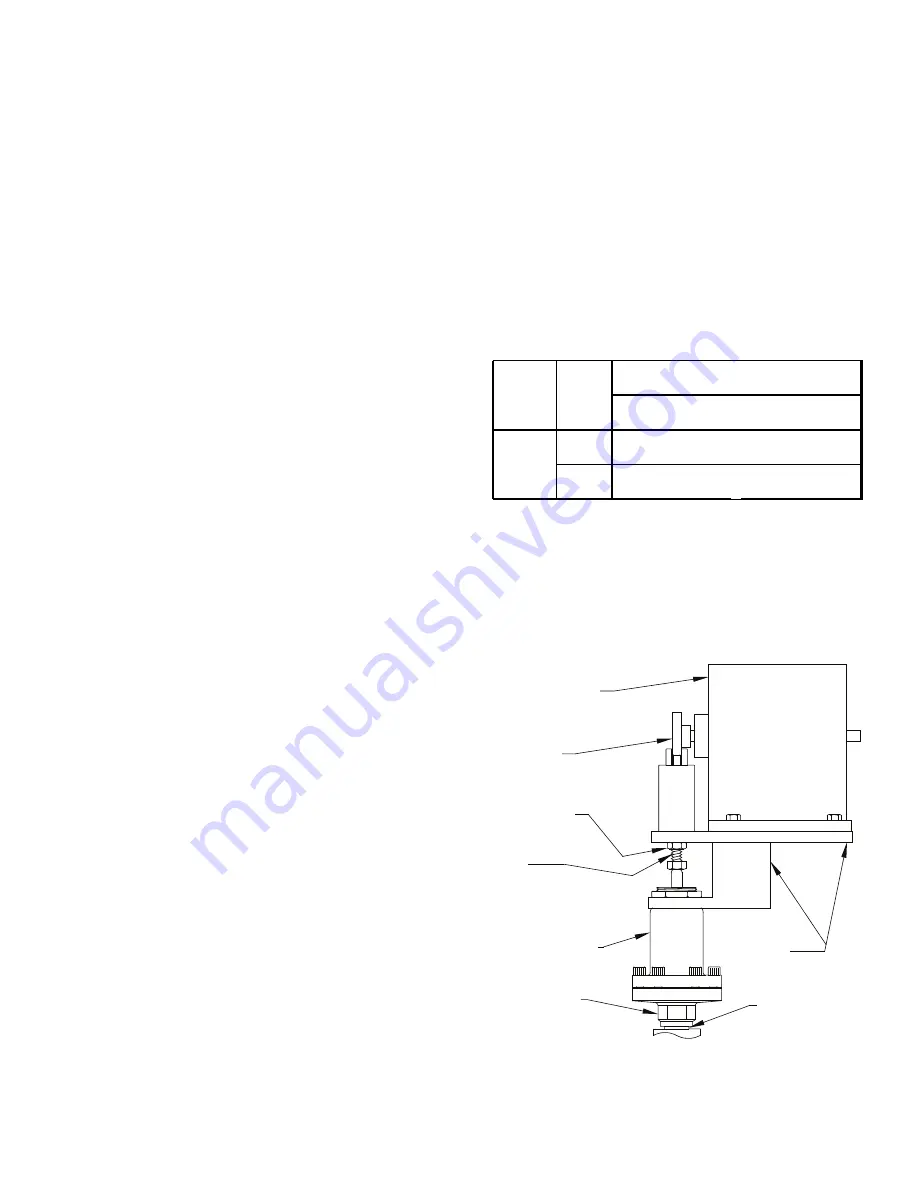
CAM
ADJUSTMENT
STEM
ADJUSTMENT
LOCKING NUT
MOTOR
MOTOR
CONTROL MODULE
BONDED
JOINT
DO NOT TURN
BRACKET
The basic Electric Motor Compensated Regulator
consists of a nonremovable control module with a motor
bracket and cam. The control module is available in either
Range A, 0 to 150 psig (0 to +10 bar g); Range V, 20" to
130 psig (– 0.67 to +9 bar g); or Range B, 30 to 300 psig
(2 to 21 bar g). The motor bracket comes mounted on
the control module and is suitable for use with any of
the HONEYWELL motors. Two cams are available: Low
Rise (standard) and High Rise. The table below indicates
the pressure change possible for each cam.
The HONEYWELL motor has 160° of rotation travel.
Motors are available for either 135 ohm control signal
input (24VAC Power input) or 4-20 mA control signal input
(120V Power input). Electric proportional thermostat
controllers (135 ohm output), electronic PID controllers
(4–20 mA output) with sensor, and 24V transformers are
available accessories.
RANGE
CAM
PRESSURE CHANGE
A,B, or V
LOW
RISE
HIGH
RISE
HONEY WELL
30 psig (2.1 bar g)
60 psig (4.1 bar g)
11
R429d
AUG 2015