40
M o u n t i n g r o o f , i n s t a l l a t i o n u n i t a n d c o l u m n s
1990
2150
150
165
55
20
45
190
680
1170
1660
1930
60
120
750
70
Hollow pipe for power supply
Inner
- Ø 25 Pg 29 (DT 100 EL40)
Inner
- Ø 25 Pg 21 (DT 100 ML40)
55
1
3
4
5
2
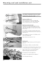
Mounting holders of the installation unit
Measurements are in relation to between the shower tray edge
and drill centres. Seal holes with silicon, free from acetic acid.
Mark left and right fixing point of the holding angle (3), punch
and drill holes
Ø6.
Secure holding angle with Phillips screw
5x35.
Mark left and right fixing point of the wall holder (1), punch
and drill holes
Ø8.
Secure wall holder with hexagonal wood screws
6x50
and
washer
6,4x10,6.
Mounting clamping ledge
Separate clamping profile (5) from clamping ledge (4).
Mark left and right on the wall the fixing points of clamping
ledge (2, punch and drill.
Use acetic acid free silicon on the clamping ledge.
Align the clamping ledge vertically. Secure clamping ledge
with Phillips screws
4x45.

