background image

31

CALIBRA

TION

8.3.  ORP CALIBRATION

The Oxidation-Reduction Potential (ORP), displayed in mV, is the voltage that results from the 
difference in potential between the platinum ORP sensor and the Ag/AgCl reference electrode. ORP 
values are not temperature compensated, although ORP values can change with temperature (e.g. 
reference electrode potential changes, sample equilibrium changes). It is important to report ORP 
values together with the reference electrode used and the temperature.
The inert platinum ORP surface provides an electron exchange site with the sample (or standard) 
and its surface. The electron exchange is typically very fast in well-poised solutions (standards for 
example), but may be more lengthy in natural water samples.
• Calibration is typically not required for a new ORP sensor, but the process does establish a baseline 

that can be used as a comparison for future validations.

• Calibration is used to compensate for changes due to contamination of the platinum surface and 

drift in the reference electrode.

A relative mV calibration can also be made to remove the voltage attributable to the Ag/AgCl reference 
electrode (to display the ORP versus a SHE (standard hydrogen electrode)). This is an arithmetic 
correction and is accurate only at the standard temperature. (For example, 

HI70224

 test solution 

reads 470 mV at 25 °C versus the Ag/AgCl reference. The ORP mV versus a SHE would be 675 mV. 
Add 205 mV to the observed value.)
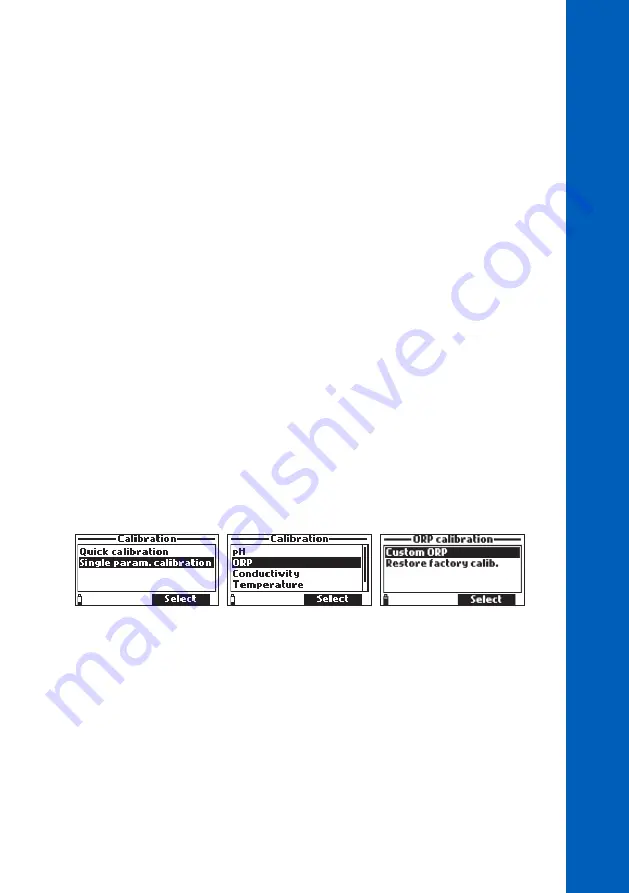
From the “Calibration” menu select “Single param. calibration” and then “ORP”.
Options:
• 

Custom ORP

: Perform a single point calibration using a custom point.

• 

Restore factory calib

.: Restore the factory calibration if a new sensor has been installed.


The calibration should be performed at temperatures between 20-26 °C.

Custom ORP Calibration Procedure

1.  Remove the shield from the probe. Rinse the probe with purified water.
2.  Fill the calibration beaker 2/3 full with the ORP test solution with a known concentration.
3.  Immerse the sensors in the solution. Raise and lower the probe several times then discard this 

solution.

4.  Fill the calibration beaker 2/3 full with the ORP test solution with a known concentration.
5.  Slowly place the sensors in the solution. Dislodge bubbles that may adhere to the sensors.

Summary of Contents for HI981954

Page 1: ...INSTRUCTION MANUAL HI981954 Multiparameter Portable Meter pH mV ORP EC TDS Resistivity Salinity Seawaterσ Atmospheric Pressure Temperature ...

Page 2: ...anna Instruments product Please read this instruction manual carefully before using this instrument This manual will provide you with the necessary information for correct use of this instrument as well as a precise idea of its versatility If you need additional technical information do not hesitate to e mail us at tech hannainst com or view our worldwide contact list at www hannainst com Dear Cus...

Page 3: ... INSTALLATION 14 5 4 SENSOR MAINTENANCE 15 6 GENERAL OPERATIONS 17 6 1 BATTERY CAPACITY REPLACEMENT 17 6 2 CONNECTING THE PROBE 18 6 3 TURNING THE METER ON 18 6 4 BASIC OPERATIONS 19 6 5 FUNCTIONAL DIAGRAM OF THE INSTRUMENT 20 6 6 HELP 20 7 PARAMETER SETUP 21 7 1 PARAMETER SELECTION 21 7 2 PARAMETER UNITS 21 7 3 PARAMETER COEFFICIENTS 24 7 4 AVERAGING 25 8 CALIBRATION 26 8 1 QUICK CALIBRATION 27 8...

Page 4: ... 10 2 PROBE STATUS 41 10 3 GLP 42 11 MEASUREMENT 44 12 LOGGING 45 12 1 ONE SAMPLE ON METER 45 12 2 START METER LOG 46 12 3 LOG RECALL 46 12 4 LOG NOTES 48 13 PC CONNECTION 49 14 PROBE DEPLOYMENT 51 15 TROUBLESHOOTING ERROR MESSAGES 53 16 ACCESSORIES 54 CERTIFICATION 57 RECOMMENDATIONS FOR USERS 57 WARRANTY 58 ...

Page 5: ...e HI7698194 1 pH ORP sensor HI7698194 3 EC TDS Salinity Resistivity sensor HI9828 20 Quick calibration standard solution 230 mL HI7698295 protective probe shield HI76981952 probe maintenance kit HI7698290 calibration beaker HI920015 micro USB cable 1 5V AA batteries 4 pcs Instrument quality certificate Probe quality certificate Instruction manual Note Save all packing material until you are sure t...

Page 6: ... sizes the digits to fit the screen with on screen graphing capability Each parameter is fully configurable HI981954 is a rugged instrument the ideal solution for a variety of water quality measurements The meter is enclosed in an IP67 rated waterproof casing and can withstand immersion in water at a depthof1mforupto30minutes TheprobefeaturesanIP68ratingforcontinuousimmersioninwater Main Features ...

Page 7: ... cm from 0 000 to 9 999 mS cm 0 01 mS cm from 10 00 to 99 99 mS cm 0 1 mS cm from 100 0 to 400 0 mS cm Accuracy 1 of reading or 1 µS cm whichever is greater Calibration Automatic single point with 6 standard solutions 84 µS cm 1413 µS cm 5 00 mS cm 12 88 mS cm 80 0 mS cm 111 8 mS cm or 1 custom point Total Dissolved Solids TDS Range 0 to 400000 ppm mg L the maximum value depends on the TDS factor ...

Page 8: ... 113 32 kPa Resolution 0 1 mmHg 0 01 inHg 0 1 mbar 0 001 psi 0 0001 atm 0 01 kPa Accuracy 3 0 mmHg within 15 C from calibration temperature Calibration Automatic at 1 custom point Temperature Range 5 00 to 55 00 C 23 00 to 131 00 F 268 15 to 328 15 K Resolution 0 01 C 0 01 F 0 01 K Accuracy 0 15 C 0 27 F 0 15 K Calibration Automatic at 1 custom point Temperature Compensation Automatic from 5 to 55...

Page 9: ...ulticonductor shielded cable with internal strength member rated for 68 kg 150 lb intermittent use Wetted Materials Body ABS Threads Nylon Shield ABS 316 SS Temperature probe 316 SS O rings EPDM 3 3 SENSOR SPECIFICATIONS HI7698194 0 Description pH sensor Measurement Type pH mV pH Measurement Range 0 00 to 13 00 pH 600 0 mV Temperature Range 5 0 to 55 0 C 23 0 to 131 0 F Color Code Red Materials Ti...

Page 10: ...temperature Junction Ceramic Body PEI Electrolyte Gel Reference Double Maintenance Solution HI703004 Storage solution Immersion Depth 20 m 65 Dimensions 118 x 15 mm HI7698194 3 Description EC sensor Measurement Type EC Measurement Range 0 0 to 200 0 mS cm 0 0 to 400 mS cm absolute Temperature Range 5 0 to 55 0 C 23 0 to 131 0 F Color Code Blue Materials Electrodes Stainless steel AISI 316 Body ABS...

Page 11: ...on displayed above them on the screen 4 Power On Off key press to turn the meter on and off 5 Lamp key press to turn the backlight on and off 6 Alphanumeric keypad press to insert alphanumeric codes 7 Arrow keys to scroll the displayed options and messages 8 HELP key press to display the context sensitive help menu 9 ESC key press to return to the previous screen 10 Soft key functions defined on d...

Page 12: ...PTION Top View 11 12 12 11 DIN connector for probe connection 12 Micro USB connector with protective cap HI7698195 Multisensor Probe pH ORP EC TDS NaCl Resistivity HI981954 2 3 1 1 Strain relief 2 Probe body 3 Protective shield ...

Page 13: ...e probe maintenance kit to clean and loosen any debris before using pH ORP Combination Sensor or pH Sensor To prepare for installation 1 Remove the shipping cap from the pH sensor 2 If the shipping cap does not contain any liquid pour HI703004 Storage solution into shipping cap 3 Place it back on the sensor and soak for at least 1 2 hour before use If HI703004 Storage solution is not available pH ...

Page 14: ... 7 2 1 3 4 5 8 1 Sensor sockets 2 EC TDS Salinity Resistivity sensor 3 Temperature sensor 4 pH sensor 5 pH ORP combination sensor 6 Strain relief 7 Probe body 8 Protective shield To install the sensors follow the steps below 1 Remove the protective shield from the probe and set it aside 2 Use the supplied silicone grease sachet and sparingly lubricate the o ring with a thin film of the grease Do n...

Page 15: ...he o rings to expand After prolonged storage or cleaning calibration of the sensors is required After use rinse the probe with tap water and dry it The pH electrode bulb must be kept moist Dry the EC sensor Check GLP data under Status to ensure the sensor is still functioning properly pH pH ORP Sensor Remove the sensor protective cap Do not be alarmed if any salt deposits are present This is norma...

Page 16: ...ing soak the sensor in HI703004 Storage solution for 30 minutes before taking measurements EC Sensor After every series of measurements rinse the probe with tap water If a more thorough cleaning is required Clean the sensor with brush found in the maintenance kit to loosen any debris Use a mild detergent to remove oily coatings Ensure that the two cylindrical holes in the sensor are free of foreig...

Page 17: ...e BEPS Battery Error Prevention System feature which automatically turns the instrument off when the batteries reach 0 To replace the batteries 1 Turn off the instrument 2 Remove the four screws on the back of the instrument to open the battery compartment 3 Remove the old batteries 4 Insert four new 1 5V AA batteries in the battery compartment while paying attention to the correct polarity Do not...

Page 18: ...E PROBE ThemultiparameterprobeisconnectedtothemeterthroughawaterproofQuickDINconnector making attaching and removing the probe an easy process When connected the probe is automatically detected With the meter off connect the probe to the DIN connector on the top of the meter Align the pins and key then push the plug into the socket 6 3 TURNING THE METER ON After connecting the sensors to the probe...

Page 19: ...for all enabled parameters up to 11 The display has a feature that automatically sizes the digits to fit the screen With fewer measurements the digits will be largest Press the keys on the alphanumeric keypad 1 7 to select number of parameters displayed at one time Use the arrow keys to scroll through the enabled parameters if they do not fit on one screen Note Pressing 7 will display up to 11 par...

Page 20: ...ter Log Start Meter Log Log Recall Log Notes Menu Meter Setup Probe Setup Quick Calibration Single Param Calibration Select Parameters Parameter Units Parameter Coefficients Averaging Meter Status Probe Status GLP Calibration Parameter Setup System Setup Status 6 6 HELP To view the context sensitive help press the HELP key Use the arrow keys to scroll through the text To return to the previous scr...

Page 21: ...ow keys to scroll through the list of available parameters Press the corresponding functional key to enable or disable the highlighted parameters or Enable Disable all option A checked box indicates that the parameter is enabled Note When the password protection is enabled authentication will be required before any parameter modification 7 2 PARAMETER UNITS Temperature Unit Option C F K Press the ...

Page 22: ... Resistivity Unit Option Ω cm kΩ cm MΩ cm Resistivity is calculated from the conductivity measurement Press the functional key to select the desired resistivity unit Seawater Sigma σ Unit Option σt σ0 σ15 Seawater sigma is calculated from the conductivity measurement and depends on water pressure temperature and salinity Pressthefunctionalkeytoselectthedesiredreferencetemperature currenttemperatur...

Page 23: ... selected resolution only Absolute EC Resolution Option Auto Auto mS cm 1 μS cm 0 001 mS cm 0 01 mS cm 0 1 mS cm 1 mS cm Press Modify and use the arrow keys to select the desired absolute EC resolution Press Select to confirm or the ESC key to return to the previous screen Auto The meter automatically chooses the range µS cm or mS cm to optimize the measurement Auto mS cm The meter automatically c...

Page 24: ...ement will be displayed with the selected resolution only 7 3 PARAMETER COEFFICIENTS EC Reference Temperature Option 20 C or 25 C This value is used for temperature compensated conductivity All EC measurements will be referenced to the conductivity of a sample at this temperature Press the functional key to select the desired EC reference temperature EC Temperature Coefficient Beta ß Option 0 00 t...

Page 25: ... or the ESC key to return to the previous screen 7 4 AVERAGING Option 1 to 20 samples Averaging is a software filter to minimize sensor noise and provide more stable readings It is particularly useful to get a representative reading of the average value from flowing water Averaging will affect all measurements If a fast response is needed this value should be kept low Press Modify to select the nu...

Page 26: ...brations than cleaner waters General calibration guidelines are listed below Set up a routine service schedule where measurement integrity is validated This is especially important for new installation sites or long deployments Inspect sensor connectors for corrosion and replace damaged sensors Inspect sensor o rings for damage and if necessary replace and lubricate with the grease supplied in the...

Page 27: ... may adhere to the sensors 6 Wait a few minutes for the system to stabilize From the Calibration menu select Quick calibration and press Select A two item calibration menu will appear pH conductivity and pH will start to blink along with the Not ready message 7 The Ready message will appear when the pH reading has stabilized Press Confirm to store the calibration point The Storing message will app...

Page 28: ...ion should follow immediately pH Calibration Procedure 1 Remove the shield from the probe and rinse the probe with purified water 2 Fill the calibration beaker 2 3 full with the first buffer solution 3 Immerse the sensors in the buffer solution Raise and lower the probe several times Discard the solution 4 Fill the calibration beaker 2 3 full with the first buffer solution 5 Slowly place the senso...

Page 29: ...ration completed will be displayed Press OK to return to the calibration menu or Measure to return to the measurement screen pH Calibration Error Messages The HI981954 displays a series of messages if an error has occurred during calibration Input out of scale the pH value is out of range The pH sensor may require replacement Check sensor the electrode may be broken very dirty or the user has atte...

Page 30: ...n or very dirty Wrong Clear old calibration erroneous slope condition These messages appear if the slope difference between the current and previous calibration exceeds the slope window 80 to 110 Press Clear to cancel the old data and continue the calibration procedure or press ESC to quit the pH calibration mode ...

Page 31: ...ectrode A relative mV calibration can also be made to remove the voltage attributable to the Ag AgCl reference electrode to display the ORP versus a SHE standard hydrogen electrode This is an arithmetic correction and is accurate only at the standard temperature For example HI70224 test solution reads 470 mV at 25 C versus the Ag AgCl reference The ORP mV versus a SHE would be 675 mV Add 205 mV to...

Page 32: ... be cleaned with the small brush from the maintenance kit A mild detergent can be used to remove oily coatings Flush the electrodes with water thoroughly after cleaning From the Calibration menu select Single param calibration and then Conductivity Options Conductivity Perform a one point calibration using a standard solution The calibration is temperature compensated Absolute conductivity Perform...

Page 33: ... probe with purified water 2 Fill the calibration beaker 2 3 full with conductivity standard solution with known concentration 3 Immerse the sensors in solution Raise and lower the probe several times Discard this solution 4 Fill the calibration beaker 2 3 full with conductivity standard solution with known concentration 5 Slowly place the sensors in the solution Dislodge bubbles that may adhere t...

Page 34: ...ys to select Salinity from the Conductivity Calibration list and press Select to start the calibration A text box window will appear Use the keypad to enter the value of the standard 5 00 to 70 00 PSU at the current temperature Press Accept to confirm the standard value 7 The stability timer will count down until the display shows the Ready message 8 Note the temperature and adjust the salinity va...

Page 35: ... and press Select to start the calibration 5 A text box window will appear Use the keypad to enter the calibration temperature 5 00 to 50 00 C Press Accept to confirm the value 6 The stability timer will count down until the display shows the Ready message 7 Press Confirm to store the calibration point The message Storing followed by Calibration completed is displayed 8 Press OK to return to the c...

Page 36: ...t box window will appear Use the keypad to enter the calibration pressure 600 0 to 1133 2 mbar Press Accept to confirm the standard value 4 The stability timer will count down until the display shows the Ready message Press Confirm to store the calibration point 5 After confirmation the Storing and Calibration completed messages are displayed 6 Press OK to return to the calibration menu or Measure...

Page 37: ... LCD Contrast 8 LCD Backlight 9 Meter Password 10 Meter ID 11 Language 12 Restore Factory Settings Time Option 12 or 24 hours The meter uses a real time clock for logging Press Modify and set the time using the keypad Press Format to change between 12 and 24 hour formats When the 12 hour format is used select AM PM then either A or P key to change Press Accept to save the option or press ESC key t...

Page 38: ...onal key will be displayed on the LCD when it goes into this mode Logging is not stopped Pressing Wake up will exit the Power save mode Key Beep Option Enabled or Disabled When enabled an acoustic signal is heard every time a key is pressed Press the functional key to select the desired option Error Beep Option Enabled or Disabled Short beep pressed key is incorrect Long beep pressed key is not ac...

Page 39: ...s entered it will not be required until the meter is turned on again To enable password protection 1 Select Meter Password and press Modify 2 Enter a password 6 digits or less in the text box and press Accept Note While typing the characters are masked with a star symbol 3 Reenter the password Press Accept to save or press ESC key to return to the menu 4 The meter returns to the Meter Setup menu a...

Page 40: ...u Restore Factory Settings This function restores measurementsettings to their originalfactory values This includes measurement units coefficients other measurement configurations and all logged data The factory calibration for the sensor channels is not affected 1 Select Restore factory settings and press Select 2 Press Yes to confirm or press No to return to the menu 9 2 PROBE SETUP Probe ID Opt...

Page 41: ...ssword Meter ID serial number and firmware version Use the arrow keys to navigate through the meter status information Press ESC key to return to the Status menu 10 2 PROBE STATUS Probe Status displays information related to the probe type connected sensors probe ID serial number and firmware version Use the arrow keys to navigate through the probe status information Press ESC key to return to the...

Page 42: ...nu pH pH GLP screen displays offset acidic slope basic slope buffers used time and date of the calibration Notes A C label near the buffer value indicates a custom point while an H indicates a Hanna Instruments standard buffer value If a quick calibration was performed buffer values are replaced with Quick calibration indication ORP ORP GLP screen displays calibration point time and date Conductiv...

Page 43: ...43 STATUS Temperature Temperature GLP screen displays calibrated point time and date Atmospheric Pressure Atmospheric pressure GLP screen displays custom calibration point time and date ...

Page 44: ...ers that are shown on the screen at one time The display will automatically resize the digits to fit the screen Use the arrow keys to scroll through the enabled parameters if they do not fit on one screen A blinking measurement value indicates that the measurement is out of range A blinking measurement unit indicates that the user calibration has not been done and is needed for accurate readings ...

Page 45: ...records with different parameter configurations 12 1 ONE SAMPLE ON METER 1 Select One sample on meter to add one set of enabled measurement parameters to the meter s memory 2 If there are existing lots on the meter select the lot to log the sample in use the suggested one by pressing OK or press Options to select from the list If no lots have been saved or to create a new lot press New Use the key...

Page 46: ... press View The meter displays a summary of all data related to the selected lot number of samples memory space used time and date of the first and last readings 2 Press View to review the log data Use the arrow keys to change the sample number in the selected lot The sample number is shown on the bottom right corner of the display Notes The values displayed for compensated conductivity and TDS ar...

Page 47: ... be plotted Press Select to view the graph 8 Use the arrow keys to move the cursor in the graph and highlight a sample The sample data is displayed below the graph 9 Press ESC to return to the parameter list 10 Press ESC again to return to the menu Note The number of lot samples that can be plotted is limited by the display resolution To view a complete graph download data to PC Delete All Lots Wh...

Page 48: ... the keypad to enter text Entry is saved with Accept To delete a remark 1 Select the remark from the list 2 Press Delete and confirm with Yes Press No or ESC to return to the previous screen Note If deleted remark is used in an existing lot information will still be available in lot data Delete All Remarks 1 Select Log notes from the Log menu then Delete all remarks 2 Confirm with Yes Press No or ...

Page 49: ... the USB cable to the meter and to a USB port on the PC 3 Turn the meter on and the message PC connected will be displayed 4 Run the HI9298194 application software 5 Press Setting button on the top of the screen and select the desired measurement units 6 To access the meter data select the Meter button on the toolbar at the top of the screen The PC Meter connection will be established and a new wi...

Page 50: ...50 PC CONNECTION Meter to PC data a Select parameter units b Select Meter from toolbar c Select Lot ...

Page 51: ...ent it is best to avoid exposure to wind foam turbulence air temperature gradients sun extended periods of high flow extended periods of high sediment and floating debris The standard operating procedures SOP for the data gathering must be upheld This typically includes pre and post deployment checks of the sensors to validate data gathered between calibrations upholding service intervals and foll...

Page 52: ...ensor surfaces face toward the flow This will minimize air bubble or fluid cavitation Limit flow rate to moderate Mount the probe at a 0 to 45 angle This will prevent the sensors pH pH ORP from becoming electrically discontinuous due to internal electrolytes flowing away from their internal cells Ensure sampling sites have easy access Regularly visit water sampling sites to check for damage to sen...

Page 53: ...eter battery is displayed if the meter batteries are too low to power the meter The meter will automatically turn off Connect the charger if using rechargeable battery or replace the alkaline batteries to continue User data corrupted is displayed when powering up and the user data stored on meter is corrupted Restart the meter If the problem persists contact your local Hanna Instruments Office Inc...

Page 54: ...ORP sensor HI7698194 3 EC sensor Cables Connectors Accessories Code Description HI710034 Shockproof silicon rubber boot HI7698290 Short calibration beaker HI7698295 Short protective shield HI7698297 Long quick release flow cell HI76981952 Probe maintenance kit with small brush small hex key o rings for probe 5 pcs 6 g sachet with silicone grease to lubricate the o rings and syringe HI9298194 PC ap...

Page 55: ...achet 25 pcs ORP Solutions Code Description HI7021L 240 mV ORP test solution 500 mL HI70224L Pool Line 470 mV ORP test solution 500 mL HI7091L Reducing pretreatment solution 500 mL 14 g set HI7092L Oxidizing pretreatment solution 500 mL HI700224P Pool Line 470 mV ORP test solution 20 mL sachet 25 pcs pH ORP Maintenance Solutions Code Description HI70614L Pool Line electrode cleaning solution 500 m...

Page 56: ...mL HI7031L 1413 μS cm calibration solution 500 mL HI7033L 84 μS cm calibration solution 500 mL HI7034L 80000 μS cm calibration solution 500 mL HI7035L 111800 μS cm calibration solution 500 mL HI7039L 5000 μS cm calibration solution 500 mL HI700304P Pool Line 12880 μS cm calibration solution 20 mL sachet 25 pcs ...

Page 57: ...em over to the appropriate collection point for recycling Ensuring proper product and battery disposal prevents potential negative consequences for the environment and human health For more information contact your city your local household waste disposal service the place of purchase or go to www hannainst com RECOMMENDATIONS FOR USERS Before using this product make sure it is entirely suitable f...

Page 58: ...d If service is required contact your local Hanna Instruments Office If under warranty report the model number date of purchase serial number see engraved on the back of the instrument and the nature of the problem If the repair is not covered by the warranty you will be notified of the charges incurred If the instrument is to be returned to Hanna Instruments first obtain a Returned Goods Authoriz...

Page 59: ...Hanna Instruments reserves the right to modify the design construction or appearance of its products without advance notice ...

Page 60: ...World Headquarters Hanna Instruments Inc Highland Industrial Park 584 Park East Drive Woonsocket RI 02895 USA www hannainst com MAN981954 Printed in ROMANIA ...

Reviews: