background image

16

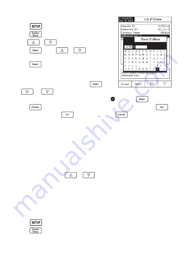
To add the GLP Data:

• Press 

 while in 

Measure mode.

• Press 

.

• Use 

 or 

 to select the GLP Data option.

• Press 

 and use 

 or 

 to highlight the

desired option.

• Press 

 to edit the desired information. The Text Editor

menu will be displayed on the LCD.

• Enter the desired information by accepting the highlighted

character which is added to the text bar, using 

. The

 and 

 keys help the user select the desired character. It is also possible to delete the last

character by positioning the cursor on the Backspace character ( ) and pressing 

.

• Press 

 to return to the GLP Data options. If the Saving Confirmation is enabled, press 

 to

accept the modified option, 

 to escape without saving or 

 to return to the editing mode.

Otherwise, the modified options are saved automatically.

Date & Time

Set the current date & time and the format in which they appear. These parameters will be displayed on the
Measure screens and also when storing measured data.

Set Date and Time

This option allows you to set the current date (year/month/day) and time (hour/minute/second).

Notes:

• Only years starting with 2000 are accepted.
• The time is set using the selected time format. For 12 Hour time format only, the AM/PM can

also be selected with 

 or 

.

Set Time Format

Choose between 12 Hour (AM/PM) time format or 24 Hour time format.

Set Date Format

Choose the desired date format from 7 available options: DD/MM/YYYY; MM/DD/YYYY; YYYY/MM/DD; YYYY-MM-DD;
Mon DD,YYYY; DD-Mon-YYYY or YYYY-Mon-DD.
To set the Date & Time:

• Press 

 while in 

Measure mode.

• Press 

.

All manuals and user guides at all-guides.com

all-guides

.com

Summary of Contents for HI5321

Page 1: ...1 HI 5321 Conductivity Resistivity TDS Salinity Temperature Bench Meter Instruction Manual www hannainst com All manuals and user guides at all guides com l l g u i d e s o m ...

Page 2: ...ned Goods Authorization number from the Technical Service department and then send it with shipping costs prepaid When shipping any instrument make sure it is properly packed for complete protection To validate your warranty fill out and return the enclosed warranty card within 14 days from the date of purchase Dear Customer Thank you for choosing a Hanna Instruments product Please read this instr...

Page 3: ...P 21 RESISTIVITY SETUP 35 TDS SETUP 37 SALINITY SETUP 39 CONDUCTIVITY CALIBRATION 41 CONDUCTIVITY MEASUREMENT 43 USP EVALUATION 44 RESISTIVITY MEASUREMENT 47 TDS MEASUREMENT 48 SALINITY CALIBRATION 49 SALINITY MEASUREMENT 50 TEMPERATURE CALIBRATION 51 LOGGING 52 PC INTERFACE 55 EC PROBE USE AND MAINTENANCE 56 TROUBLESHOOTING GUIDE 57 ACCESSORIES 58 All manuals and user guides at all guides com ...

Page 4: ...th built in temperature sensor and ID HI 76404W Electrode Holder Conductivity Calibration Solutions Kit 12 Vdc Power Adapter Instruction Manual HI 5321 01 is supplied with 12 Vdc 115 Vac adapter HI 5321 02 is supplied with 12 Vdc 230 Vac adapter Note Save all packing material until you are sure that the instrument works properly Any defective item must be returned in the original packing with the ...

Page 5: ...obe offset calibration Single fixed point salinity calibration Percent Scale only AutoHold feature to freeze first stable reading on the LCD Two selectable alarm limits for conductivity resistivity TDS salinity Three selectable logging modes Automatic Manual or AutoHold Up to 100 logging lots for automatic or manual modes and up to 200 USP reports Selectable sampling period for automatic logging 1...

Page 6: ...AR PANEL 1 Liquid Crystal Display LCD 2 Capacitive touch keypad 3 ON OFF switch 4 Power adapter socket 5 Conductivity probe connector 6 USB connector FUNCTIONAL DESCRIPTION All manuals and user guides at all guides com l l g u i d e s o m ...

Page 7: ...rrent menu e g and in Measure mode LCD GENERAL DESCRIPTION To enter exit calibration mode To select the desired measurement mode Conductivity Resistivity TDS Salinity To enter Setup System Setup Conductivity Setup Resistivity Setup TDS Setup or Salinity Setup and to access Log Recall function To obtain general information about the selected option operation All manuals and user guides at all guide...

Page 8: ...1 m c S m 0 0 0 8 m c S m 8 8 2 1 m c S m 0 0 0 5 m c S m 3 1 4 1 m c S µ 0 0 4 8 n o i t i n g o c e r e b o r p y t i v i t c u d n o C s e Y n o i t a s n e p m o c e r u t a r e p m e T r e t a w l a r u t a n r a e n i l n o N r a e n i L d e l b a s i D t n e i c i f f e o c e r u t a r e p m e T C 0 0 0 1 o t 0 0 0 e r u t a r e p m e t e c n e r e f e R C 0 0 3 o t C 0 5 s e l i f o r P n ...

Page 9: ... R K 1 0 F 1 0 C 1 0 y c a r u c c A e b o r p t u o h t i w K 2 0 F 4 0 C 2 0 n o i t a r b i l a C C 0 0 1 0 5 0 s t n i o p 3 n i n o i t a r b i l a c r e s U l e n n a h c t u p n I y t i n i l a S S D T y t i v i t s i s e R y t i v i t c u d n o C e c a f r e t n i C P B S U d e t a l o s i o t p O P L G s t n i o p n o i t a r b i l a c t n e i c i f f e o c n o i t a s n e p m o c e r u t...

Page 10: ...er objects at the meter power on Turn the instrument on from the power button located on the rear panel of the instrument Please wait until the instrument finishes the initialization process Note It is normal for the loading process to take a few seconds If the instrument doesn t display the next screen restart the meter using the power switch If the problem persists contact your dealer OPERATIONA...

Page 11: ...e instrument will display the detailed GLP data For measurement mode s the following display configurations are available Basic Graph and Log History A GLP display is available for Conductivity and Salinity Percent scale Basic The main measured value and it s units are displayed on the LCD along with the temperature value temperature probe status and basic calibration information when available To...

Page 12: ...in online graph To Zoom Graph Press then and will appear in virtual keys Use and to move along the X Time axis of the graph Press to access the zoom menu for Y axis Use or for zooming Y parameter axis Press to return to the main menu When the off line graph is displayed Use the arrow keys to move along the X Time and Y parameter axes of the graph Press to access the zoom menu for X and Y axes Use ...

Page 13: ...The Choose Display Configuration message will be displayed in the Reminder messages area Press The instrument will display the log history regarding the selected Measure mode Notes When an alarm condition is active the logged records will have an exclamation mark If logged in Auto Hold logged records will have an H If another Measure mode is selected the Log History will reset If the temperature u...

Page 14: ... Setup option Use or to highlight the desired option Press to access the selected option The following is a detailed description of the System Setup option screen Beeper This option allows the user to turn an acoustic warning signal on or off This function can be used to signal 4 different events a stable signal an alarm state when every key is pressed or when an incorect key is pressed Enable or ...

Page 15: ...s option to customize log GLP information with specific identification data When enabled these ID tags will be included in the GLP section of all data logs Each data field can use up to 10 characters The five available fields are Operator ID used to add the name of the operator Instrument ID used to name an instrument with a discrete name location or number Company Name used to include the Company...

Page 16: ...the editing mode Otherwise the modified options are saved automatically Date Time Set the current date time and the format in which they appear These parameters will be displayed on the Measure screens and also when storing measured data Set Date and Time This option allows you to set the current date year month day and time hour minute second Notes Only years starting with 2000 are accepted The t...

Page 17: ... the user that a date time conflict has occured and some time dependent modes could work improperly e g Measure GLP Log LCD Setup This option allows the user to set the Contrast the Backlight of the LCD and the Backlight Saver The Contrast parameter can be adjusted within 7 steps while the Backlight parameter within 8 steps The Backlight Saver can be set from 1 to 60 minutes or it can be OFF disab...

Page 18: ...n allows the user to choose a desired color palette To select the Color Palette Press while in Measure mode Press Use or to select the Color Palette option Press and use or to highlight the desired color Press to confirm your selection and return to the System Setup menu or press to return to the System Setup menu without changing 1 r o l o C t x e t e u l b d n u o r g k c a b e t i h W 2 r o l o...

Page 19: ...ervice for factory calibration To view the Meter Information Press while in Measure mode Press Use or to select the Meter Information option Press to acces the Meter Information menu Press to return to the System Setup menu Serial Communication This option allows the user to set the desired speed for the serial communication baud rate in bps The meter and the PC program must have the same baud rat...

Page 20: ... settings and reset the instrument to the default factory settings To restore the Factory Settings Press while in Measure mode Press Use or to select the Restore Factory Settings option Press to confirm your selection A pop up menu will be displayed asking for confirmation Press to confirm your selection and return to the System Setup or press to return to the System Setup menu without restoring d...

Page 21: ...d at a moment s notice A profile is a sensor setup complete with measurement units logging and display preferences calibration standards Standards including custom setup of the Display screen for measurement i e graphing GLP and any other sensor configuration Once saved the exact same profile can be used at another time This is a handy feature if the meter is used occasionally for additional appli...

Page 22: ...ight the desired character and then press to add it to the text bar It is also possible to delete the last character by positioning the cursor on the Backspace character and pressing Press to return to the previous menu If the Saving Confirmation is enabled press to accept the modified option to escape without saving or to return to the editing mode Otherwise the modified option is saved automatic...

Page 23: ...t the desired profile and press Press to return to the previous menu Reading Mode This option allows the user to select between Direct Direct AutoHold or Direct USP conductivity reading modes Note All three selections permit conductivity to be changed to resistivity TDS and salinity via the key To set the reading mode Press while in Conductivity mode Press Use or to highlight the Reading Mode opti...

Page 24: ...from the following options Linear the meter will automatically compensate the conductivity using the following formula where Cref conductivity at reference temperature CI conductivity at temperature of measurement α compensation coefficient TI temperature in C Tref reference temperature Non Linear recommended for measuring the conductivity of the natural water in accordance with the ISO 788 1985 I...

Page 25: ...C To set the reference temperature Use or to highlight the Temperature option Press and then use or to highlight the Reference Temperature option Press and then use or to increase decrease the value Press to save or press to cancel operation Press to confirm your selection or press to cancel operation Note Whatever form of compensation is used the reading will not beasaccurateastakingareadingofthe...

Page 26: ...ell Constant The conductivity probe can be calibrated using the conductivity standards or by entering the cell constant of the probe by the user Using standard solutions The probe and the meter can be calibrated with a single standard or with multiple standards up to four points choosing from 6 Hanna standards 84 µS cm 1413 µS cm 5 0 mS cm 12 88 mS cm 80 0 mS cm 111 8 mS cm or using the custom sta...

Page 27: ...choose Single Point calibration The following options are available for calibration Standard Recognition The user can choose between Automatic recognition from 6 Hanna standards available or User Standard when custom standards are used for calibration Press while in Conductivity mode Press Use or to highlight the Calibration option Press and then use or to highlight the Standard Recognition option...

Page 28: ... Set Reminder Period Daily reminder the user can set the time of day when the reminder is to appear Periodic reminder the user can set the time from the last calibration days hours and minutes after which the reminder appears To set the reminder period Press while in Conductivity mode Press Use or to highlight the Calibration option Use or to highlight the Set Reminder Period option Press and use ...

Page 29: ...and return to the Calibration options Cell constant manual editing The conductivity probe can also be calibrated by entering the cell constant value To edit the cell constant value Press while in Conductivity mode Press Use or to highlight the Cell Constant option Press toresetthecellconstantvaluetodefault 1 0000 cm Use to increase decrease the value Press to confirm the new value or press to exit...

Page 30: ...D Increment mode and Edit Sample ID ID Increment Choose None to identify a sample with a text tag Choose Automatic to identify a sample with a numeric tag This number will be incremented by one for each new lot log but it can also be altereted manually here This number does not increment for each manual log sample This will be automatically incremented when a New Lot will be selected To select the...

Page 31: ...e last character by positioning thecursorontheBackspacecharacter andpressing Press to return to Sample ID option If the Saving Confirmation is enabled press to accept the modified option to escape without saving or to return to the editing mode Otherwise the modified options are saved automatically For numeric editing use or keys Press to save the current value or press to cancel operation Log Not...

Page 32: ...Use or to highlight the Log option Press and use or to highlight the Logging Type option Press and use or to highlight the desired option Press to confirm your selection or press to cancel operation Logging Data Configuration This option allows the user to select which parameters will accompany a log File Date Time Calibration Data Sample ID Instrument ID Operator ID Company Name Additional Info 1...

Page 33: ...lot can be created only if the Logging Type is set as Manual To generate a New Lot Press while in Conductivity mode Press Use or to select the Log option Press and use or to highlight the New Lot option Press to generate a new manual lot A pop up menu will be displayed asking for confirmation Press to confirm or press to escape without saving and return to the Log options Alarm This option allows ...

Page 34: ...light the Alarm State option Press and use or to highlight the desired option Press to confirm your selection or press to cancel operation Alarm Limits This option allows the user to set the alarm limits for the measured value Note The Alarm High value can not be lower than the Alarm Low value Press while in Conductivity mode Press Use or to select the Alarm option Press and use or highlight the A...

Page 35: ...ect the desired option Press to confirm your selection The following is a description of the Resistivity Setup option screens Profile see Conductivity Setup section RESISTIVITY SETUP Reading Mode This option allows the user to select between Direct and Direct AutoHold resistivity reading modes To set the Reading Mode Use or to highlight the Reading Mode option Press to select Direct Direct AutoHol...

Page 36: ... in Resistivity mode Press Use or to highlight the Units option Press to confirm and then use or to highlight the desired unit Press to confirm or press to cancel operation Sample ID see Conductivity Setup section Log see Conductivity Setup section Alarm see Conductivity Setup section All manuals and user guides at all guides com l l g u i d e s o m ...

Page 37: ...wing is a description of the TDS Setup option screens Profile see Conductivity Setup section Reading Mode see Resistivity Setup section Temperature see Conductivity Setup section Units This option allows the user to set the TDS measuring unit ppm mg L ppt g L or AutoRanging units To select the suitable unit Press while in TDS mode Press Use or to highlight the Units option Press to confirm and the...

Page 38: ... 70 Example TDS factor 0 5 µS cm x 0 41 0 205 ppm NaCl The default value is 0 50 This option allows the user to set the TDS factor Press while in TDS mode Press Use or to highlight the TDS Factor option Press to confirm your selection and use or to increase decrease the value Press to confirm your selection or press to cancel operation Sample ID see Conductivity Setup section Log see Conductivity ...

Page 39: ...ity Setup section Reading Mode see Resistivity Setup section Temperature see Conductivity Setup section To set one of the Temperature options Press while in Salinity mode Press Use or to highlight the Temperature option Press and then use or to highlight the desired Temperature option you wish to modify Press and then use or to highlight the desired option for Temperature Source Unit options or us...

Page 40: ...inity Measurement for a description of these scales The meter has three ocean salinity scales Natural Sea Water 1966 Practical Scale 1978 Percent Scale To select the desired salinity measurement scale Press while in Salinity measure mode Press Use or to highlight the Salinity Scale option Press and use or to highlight the desired option Press to confirm your selection or press to cancel operation ...

Page 41: ...ctical Sea Water Salinity readings are automatically derived from the conductivity readings so conductivity calibration is required OFFSET CALIBRATION The meter allows the user to calibrate the probe for an offset Press and then press Select the automatic standard recognition see Conductivity Setup Calibration Leave the dry probe in the air infinite resistance Enter in calibration mode by pressing...

Page 42: ...andard value Press to finish the calibration or to abort calibration The probe should be rinsed in deionized water Shake off excess water Note The calculated cell constant will be used for the whole range Multi Point Calibration Up to 4 calibration points can be performed in order to increase the measurement accuracy over a larger measurement range Select the multi point calibration see Conductivi...

Page 43: ...ed standards Make sure the instrument has been calibrated before taking conductivity measurements DIRECT MEASUREMENT To measure the conductivity of a sample using the Direct reading mode Press and then to select conductivity measure mode Select the Direct reading mode see Conductivity Setup The conductivity probe should be rinsed with deionized water Shake off excess water If possible rinse probe ...

Page 44: ...been calibrated in conductivity standards in the lowest measurement range Press and then select the desired USP stage In this measure mode the user can check for water quality using the United States Pharmacopeia standard USP 645 guidelines for water for injection This USP standard consists of three stages one in line and two off line tests as followings DIRECT AUTOHOLD MEASUREMENT To measure cond...

Page 45: ...esponding conductivity value in the table on the next page If the measured conductivity is lower than the conductivity in the table then the water meets the USP requirements Otherwise proceed to Stage 2 testing Stage 1 steps Press from the keypad An instruction prompt will pop up Using measurement technique outlined in direct measurement place probe into sample Press The user may Edit the USP fact...

Page 46: ... 92000 software Note A separate pH meter and sensor is required Stage 3 this is an off line test that studies the pH and CO2 If the water sample has failed Stage 1 and Stage 2 tests Stage 3 testing must be conducted To perform this test pH measurement is required Have a calibrated pH sensor Stage 2 this is an off line test To perform this test Store the water sample in an enclosed clean container ...

Page 47: ... 2 test and increase its ionic strength for a pH measurement at 25 C Use 100 mL of Stage 2 water and add 300 µL saturated KCl to the sample Calibrate a pH sensor in pH 4 01 and pH 6 862 or 7 01 buffers Thermally equilibrate the sample to 25 0 1 C Measure sample with the calibrated pH sensor The pH of sample must be between 5 0 and 7 0 pH Record the pH and round it to the nearest 0 1 pH Find the me...

Page 48: ...onductivity measurement see Conductivity Measurement section DIRECT AUTOHOLD MEASUREMENT To measure resistivity of a sample using the Direct AutoHold reading mode Select the Direct AutoHold reading mode see Resistivity Setup section Proceed the same as for the conductivity measurement see Conductivity Measurement section Press and then to select resistivity measure mode Select the Direct reading m...

Page 49: ...ay from the wall or bottom of the container Enter in calibration mode by pressing Wait for measurement to stabilize Press to finish salinity calibration or press to cancel calibration CALIBRATION MESSAGES Wrong standard solution Check the standard solution This message appears when the difference between the reading and the value of the selected standard is significant If this message is displayed...

Page 50: ...ts and k 0 0162 and Seawater temperature coefficient rT c0 c1 T c2 T2 c3 T3 c4 T4 S a0 a1 RT 1 2 a2 RT a3 RT 3 2 a4 RT 2 a5 RT 5 2 T 15 b0 b1 RT 1 2 b2 RT b3 RT 3 2 b4 RT 2 b5 RT 5 2 1 k T 15 R C S T P RP RT rT C 35 15 10 K15 C S 15 0 C KCl 15 0 C 35 15 rT R15 CT sample RT R RP rT RP 1 P A1 A2 P A3 P2 1 B1 T B2 T2 B3 R B4 R T where R15 is the conductivity ratio and Salinity is defined by the follo...

Page 51: ...channel Press to start the temperature calibration Adjust the temperature preset value using or when necessary Insert the EC probe into the beaker with water at 0 C Wait for measurement to stabilize and then press to confirm the calibration point Repeat the previous steps for 50 C and 100 C Save the calibration Press to return to measure mode Note Press if you want to clear the temperature user ca...

Page 52: ...and Manual Log Real time continuous measurements are on display and snapshots of measurement data are stored in the Manual log when the user presses Subsequent snapshots will be added to the same Manual Lot every time the is depressed unless New Lot is selected under Log options Note When the is pressed the lot ID along with the current record number will appear for short time on the selected chan...

Page 53: ...rect AutoHold Reading Mode and Auto Hold Log Press and then keys to initiate and automate the capture of stable data which is stored in the Recall Manual Log file During the process AutoHold will flash until the stability criteria is reached and then the screen freezes in Auto Hold mode the data is logged and marked with an H The virtual key returns operation to Real time continuous measurement Pr...

Page 54: ...ormation last calibration date and calibrated standards if a calibration has been performed on the selected mode and the logged values measured value temperature value temperature compensation mode and the logging time Note For automatic logging only it is possible to view the plotted graph Press to display the graph By pressing it is possible to move the graph along the X or Y axis with the arrow...

Page 55: ...so be deleted whenever Limited Automatic Logging Space or Automatic Log Is Full message appears on the LCD in the Reminder messages area Data transmission from the instrument to the PC can be done with the HI 92000 Windows compatible software optional HI 92000 also offers graphing and on line help features Data logged on the HI 5321 meter can be exported to the most popular spreadsheet application...

Page 56: ...le is measured within the sleeve of the probe If required wait for the probe to reach thermal equilibrium with the sample PERIODIC MAINTENANCE Inspect the probe and the cable The cable used for connection to the instrument must be intact and there must be no points of broken insulation on the cable Connectors must be perfectly clean and dry Rinse off any salt deposits with water If more cleaning i...

Page 57: ... s n i s i e b o r p y f i r e V t n s e o d t n e m u r t s n i e h T e r u t a r e p m e t e h t e r u s a e m e b o r p e h t m o r f e r u t a r e p m e t e b o r p e h T e h T n e k o r b s i r o s n e s s a t e s s i e c r u o s e r u t a r e p m e t l a u n a m t e S e b o r p e h t e c a l p e R s a e c r u o s e r u t a r e p m e t e h t c i t a m o t u a r o e t a r b i l a c o t s l i a...

Page 58: ...0 µS cm 230 mL bottle HI 7030L 12880 µS cm 500 mL bottle HI 8030L 12880 µS cm 500 mL FDA approved bottle HI 7034M 80000 µS cm 230 mL bottle HI 7034L 80000 µS cm 500 mL bottle HI 8034L 80000 µS cm 500 mL FDA approved bottle HI 7035M 111800 µS cm 230 mL bottle HI 7035L 111800 µS cm 500 mL bottle HI 8035L 111800 µS cm 500 mL FDA approved bottle HI 7037L 100 NaCl sea water standard solution 500 mL OTH...

Page 59: ...steps to correct interferences Any variation introduced by the user to the supplied equipment may degrade the instruments EMC performance To avoid electrical shock do not use these instruments when voltages at the measurement surface exceed 24 Vac or 60 Vdc To avoid damage or burns do not perform any measurement in microwave ovens Hanna Instruments reserves the right to modify the design construct...

Page 60: ...al Park 584 Park East Drive Woonsocket RI 02895 USA Technical Support for Customers Tel 800 426 6287 Fax 401 765 7575 E mail tech hannainst com www hannainst com Local Sales and Customer Service Office MAN5321 02 15 All manuals and user guides at all guides com ...

Reviews: