background image

40

OPERA

TIONAL GUIDE

8.4.  LOGGING

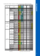
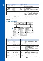
The controller logging system offers an automatic save mode for all parameters (pH, ORP, Temperature) and the following events:
• High and Low alarms
• Overtime errors
• Hold Input
• Remote Hold
• Low tank level for acid or chlorine tanks 
• Manual Mode
• Power failure 
• Probe being reconnected
Logged data is stored in the internal controller memory.
A new log is generated if any of the following settings are changed: controller ID, the date /time, decimal point or any setting 
from pH / ORP / Temperature menu.

8.5.  LOG RECALL

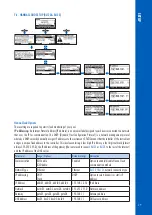
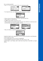
Logged data can be viewed on the controller in standard mode or plot mode.
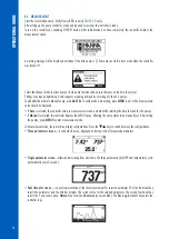
• To access the logged data, press the 



 keys from measurement mode, to display the real-time plot mode screen. Press 

Rec. Log

 key.

• The controller can hold up to 100 logs. 
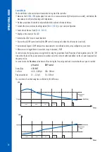
• The Log Recall summary screen displays the list with all available logs, with the most recent log displayed at the top.

• If the settings are changed, multiple logs from same day will be displayed with different index.

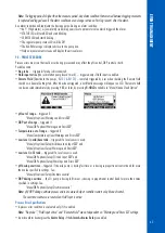
The 

Log Recall

 function can be accessed via two screens. To switch between the screens use 

-->

 and 

<--

 keys.

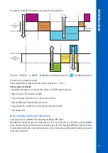
• Use the 



 keys to select the day.

• To view the logs in plot mode, press 

Plot

.

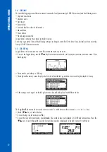
• To view the logs in Normal mode, press 

Details

. The record values are displayed: pH, ORP and temperature. Press the 



 keys, to scroll through the records. Current index number is displayed in the right corner of the title bar.

   

Summary of Contents for BL120

Page 1: ...INSTRUCTION MANUAL SWIMMING POOL CONTROLLERS BL120 BL121 BL122 BL123 WITH CLOUD CONNECTIVITY...

Page 2: ...a Hanna Instruments product Please read this instruction manual carefully before using this instrument This manual will provide you with the necessary information for correct use of this instrument a...

Page 3: ...INES 15 6 2 INSTALLATION STEPS 15 6 3 MOUNTING RECOMMENDATIONS FOR SADDLE 18 6 4 CONNECTING THE PROBE TO THE PUMP CONTROLLER 19 6 5 INSTALLING THE ASPIRATION FILTER 20 6 6 INSTALLING THE INJECTOR 20 6...

Page 4: ...LE OF CONTENTS 9 4 SYSTEM ERRORS 44 10 MAINTENANCE 46 10 1 ELECTRODE CONDITIONING MAINTENANCE 46 10 2 PUMP TUBING REPLACEMENT 46 11 ACCESSORIES 48 CERTIFICATION 52 RECOMMENDATIONS FOR USERS 52 WARRANT...

Page 5: ...nd injection tubing 5 5 m Aspiration filter 2 pcs 7 01 pH Buffer solution 3 sachets 4 01 pH Buffer solution 3 sachets 470 mV ORP test solution 3 sachets Power cable Instrument quality certificate Inst...

Page 6: ...g the pool controller To remove stabilizer from the pool the pool must be drained and cleaned Always disconnect the pool controller from power when making electrical connections Do not access the larg...

Page 7: ...bration adjustable single point ORP mV calibration adjustable single point Temperature compensation Automatic 5 0 to 105 0 C 23 0 to 221 0 F for pH pH Controller Proportional feed using adjustable set...

Page 8: ...he instrument Alarm settings Dosing settings General settings System Meter information model FW version OS version serial number Probe information type FW version serial number The Remote Hold mode is...

Page 9: ...supply 100 240 Vac Power consumption 15 VA Environment 0 50 C 32 122 F Max 95 RH non condensing Dimensions 245 x 188 x 55 mm 73 mm with pumps 9 6 x 7 4 x 2 2 2 9 with pumps Weight 1700 g 60 oz Casing...

Page 10: ...d to it Measurement data stored on the probe is transferred to the controller via a digital connection thus eliminating noise and static due to high impedance signals carried by the cable BL12X swimmi...

Page 11: ...OUT chlorine 8 Chlorine dosing pump 9 Cable gland seals 10 Probe connector 11 Keypad area 12 USB port host 13 Liquid Crystal Display LCD 14 LED area 15 Status LED 16 Service LED 17 Chlorine pump statu...

Page 12: ...ontroller from power when making electrical connections Do not access the larger rear panel User serviceable terminals are found in the small sub panel only Use a Phillips head screwdriver and remove...

Page 13: ...not access the larger rear panel User serviceable terminals are found in the small sub panel only There are four openings for wiring The left rear openings for power and digital input wiring The left...

Page 14: ...seal to reach intended terminals 5 Insert the rubber seal into the housing then tighten the connection by turning the knurled nut clockwise Nut Housing Rubber seal Note For BL123 always connect the an...

Page 15: ...For in line installation the probe saddle should be positioned after the pool filter within 2 m distance Caution Use gloves protective clothing and eye protection goggles when working with injectors...

Page 16: ...CE STATUS BL123 7 7 5 1 6 6 4 2 3 8 9 9 Position Component description 1 Pool controller 2 pH ORP temperature electrode 3 Electrode fitting 4 Flexible tubing for pump input 5 Rigid tubing for pump out...

Page 17: ...rine pH SWIMMING POOL CONTROLLER SERVICE STATUS BL123 ACID TANK CHLORINE TANK 1 2 3 4 5 6 8 7 9 9 10 10 8 12 12 12 12 11 11 Position Component description 1 Pool controller 2 pH ORP temperature electr...

Page 18: ...e the O ring 8 provided into the upper saddle Probe Saddle In line Configuration Thread Size Drill Size BL120 550 50 mm pipe 1 thread 29 mm 32 mm 1 14 1 26 BL120 563 63 mm pipe 1 thread 29 mm 32 mm 1...

Page 19: ...e installation 1 Remove protective cap and verify the O ring is in place 2 Insert the nut onto the probe O ring Protective cap Nut adapter 3 Carefully screw the adapter onto the probe taking care not...

Page 20: ...istaltic pump inlet onto the tubing Slide the end of tubing over the fitting of the peristaltic pump tubing Slide compression fitting up over tubing Tighten the fitting 6 6 INSTALLING THE INJECTOR Cut...

Page 21: ...he flow cell cap Place an O ring 4 onto the flow cell cap 1 and insert the cap onto the end of the flow cell tubing 2 with the hole in the side Screw the flow cell nut 3 into place over the flow cell...

Page 22: ...BL123 Measurements and data storage are accessible from a PC tablet or phone with an internet connection Multiple registered devices may be connected Go to www hannacloud com webpage and follow the r...

Page 23: ...controller menu is grouped into seven categories Acid or base pump control Cl2 pump control pH options CAL Setup GLP ORP options CAL Setup GLP Temperature options Setup Hanna Cloud options BL122 BL12...

Page 24: ...24 SETUP BL122 BL123 OVERVIEW see HANNA CLOUD SETUP...

Page 25: ...format Key Beep Enable Disable Disabled Enables Disables the accoustic signal for key pressing Alarms Errors Beep Enable Disable Enabled Generated when a new event is triggered Decimal Point Comma Poi...

Page 26: ...umps 7 3 PARAMETERS SETUP OVERVIEW 8 0 pH 900 mV 200 mV C Disabled 105 0 C 5 0 C 5 min Disabled 6 0 pH Disabled 30 min Note The analog outputs AO1 AO2 AO3 are only available for BL121 BL123 pH Paramet...

Page 27: ...d Enables Disables the low level input in acid tank The minimum adjustable value for alarm high is related to the value assigned to alarm low if enabled The maximum adjustable value of alarm low is re...

Page 28: ...gh event if continuous for more than 5 seconds Alarm High Enable Disable Disabled Enables Disables the temperature high alarms Alarm Low 0 0 to High 0 1 C 0 1 C 32 0to High 0 1 F 0 1 F 10 0 C 49 9 F M...

Page 29: ...four digit IP address a four digit netmask almost always 255 255 255 0 the IP address of the gateway the router used to connect BL122 or BL123 to the rest of the internet and the IP address of the DN...

Page 30: ...om General Setup screen and press Modify to activate the feature A five digit password has to be entered next To change the digit value press the keys To move to the next digit press the arrow functio...

Page 31: ...select the minimum and maximum limit values for the parameter The maximum and minimum values for each parameter are defined in the parameter Setup menu For example if the pH was assigned to analog ou...

Page 32: ...n one for rinsing the electrode and one for calibration If measuring in the acidic range use 4 01 pH as the first buffer and 7 01 pH as the second buffer If measuring in the alkaline range use 7 01 pH...

Page 33: ...e difference between the pH reading and the value of the selected buffer is too high Check that correct calibration buffer has been used Invalid Slope Displayed when the calculated slope is outside of...

Page 34: ...save the calibration The controller and the probe should have previously been calibrated in two buffers so an electrode slope has been determined Press MENU from measurement mode Press the keys to sel...

Page 35: ...R key Press YES to confirm or NO to exit and return in the calibration screen A confirmation message is displayed next After pressing CFM in calibration DONE message is displayed Rinse the probe in a...

Page 36: ...If Auto is selected the controller enters in measurement screen automatically selecting the Auto function for the pumps If Manual is selected the controller displays the MENU screen allowing the pump...

Page 37: ...ation pump doesn t work The HOLD mode was remotely activated Screen status messages BL122 BL123 Connecting Connected Disconnected Physical network issues Disconnected Cloud connection issues Sending m...

Page 38: ...ock the ORP control is running only when the pH set point is reached Automatically logs pH ORP temperature measurements last calibration data setup configuration event data Allows access to logged dat...

Page 39: ...arms and or process errors are active when the Hold Input or Remote Hold events are active pump operation has exceeded time set in the Overtime safety timer selection upon entering Setup Manual Auto P...

Page 40: ...ard mode or plot mode To access the logged data press the keys from measurement mode to display the real time plot mode screen Press Rec Log key The controller can hold up to 100 logs The Log Recall s...

Page 41: ...ted Transfer in progress is displayed on screen while the data is transferred and saved to the USB stick Data is saved in a folder named after the controller ID All logs can be deleted by selecting De...

Page 42: ...ired alarm is enabled the alarm level is exceeded and the set timeout value defined to trigger the alarm was not exceeded Menu General Events Timeout x min Overheating dosing delay pump control is dis...

Page 43: ...sing YES or later by pressing R HOLD available in Menu Hanna Cloud Option pH out of range triggered if Menu pH options Warnings and Errors ORP out of range triggered if Menu ORP options Warnings and E...

Page 44: ...ll put the controller in ERROR mode to avoid unpredictable behavior When the controller enters ERROR mode it Stops the dosing pumps Stops the logging Activates the alarm relay relay not energized Gene...

Page 45: ...uto Off Auto Off Auto Off Auto Off Auto Off Auto Off Auto Off Auto Auto Off Auto Auto Off pH Under Over range Auto Off Auto Off ORP Under Over range Auto Off Auto Off Temp Under Over range Auto Off Au...

Page 46: ...eved by installing the electrode in such a way that it is constantly in the flow cell or the pipe filled with the sample When not in use replace the solution in the protective cap with a few drops of...

Page 47: ...47 MAINTENANCE 6 Fix the plastic holder in its place on the right and left side 7 Place the plastic cover Reattach the tubings to the pumps...

Page 48: ...Fittings kit for 50 mm pipe BL120 163 Fittings kit for 63 mm pipe BL120 175 Fittings kit for 75 mm pipe BL120 200 Pool controller aspiration filter BL120 201 Pool controller injector thread Aspiratio...

Page 49: ...pump cover with screw BL120 400 Flow cell probe adapter kit BL120 401 Flow cell valve BL120 402 Flow cell tubing 10 m BL120 410 Flow cell for BL120 BL121 BL122 BL123 BL120 411 Flow cell panel spare p...

Page 50: ...pipe 1 thread BL120 575 Probe saddle for 75 mm pipe 1 thread BL120 601 Plastic nipple 2 x 1 2 with O rings BL120 602 Metal nipple 12 x 1 2 2 pcs BL120 603 Elbow for glass flow cell BL120 604 O ring f...

Page 51: ...mL 25 pcs HI70010P pH 10 01 buffer sachets 20 mL 25 pcs HI7004L pH 4 01 buffer solution 500 mL HI7007L pH 7 01 buffer solution 500 mL HI7010L pH 10 01 buffer solution 500 mL ORP SOLUTIONS HI7021L ORP...

Page 52: ...ich it is used Any variation introduced by the user to the supplied equipment may degrade the controller s performance For your and the controller s safety do not use or store the controller in hazard...

Page 53: ...Hanna Instruments reserves the right to modify the design construction or appearance of its products without advance notice...

Page 54: ...World Headquarters Hanna Instruments Inc Highland Industrial Park 584 Park East Drive Woonsocket RI 02895 USA www hannainst com MANBL12X Printed in ROMANIA...

Reviews: