background image

31


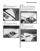
Step 3

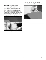
Remove the flap linkage stay from the wing. Be careful 

when removing the stay that you don't damage the wing. 

You can either use a rotary tool or razor saw to cut the tab 

flush with the wing.


Step 4

Select the correct servo hatch by checking the alignment 

for the servo arm on the plate with the one on the wing.


Step 5

Install the recommended servo hardware (grommets and 

eyelets) supplied with the servo. Temporarily install a long 

half servo arm (JRPA212) onto the servo and position 

the servo onto the hatch so the servo arm is centered in 

the notch. Once satisfied, mark the location for the servo 

mounting blocks using a felt-tipped pen.

Note

: Check to make sure your servo does 

not hang off one end of the servo hatch. 

If so, reposition the servo. Having the 

servo fully on the hatch is more important 

than having the servo arm centered.


Step 6

Locate two 3/8 in x 3/4 in x 3/4 in (9.5mm x 19mm x 

19mm) servo mounting blocks. Use 6-minute epoxy to 

glue the blocks to the hatch. Let the epoxy fully cure 

before proceeding to the next step.

Section 14: Adding Flap Servos

Summary of Contents for F-22 Raptor PTS

Page 1: ...thout droops and tip extensions 675 sq in 43 55 sq dm Weight 7 0 7 5 lb 3 18 3 40 kg Radio JR Sport 600X 6 channel system installed Engine Evolution Engines Trainer Power System installed Lockheed Martin and F 22 RAPTOR are either registered trademarks or trademarks of Lockheed Martin Corporation in the USA and or other countries used under license by Horizon Hobby Inc Assembly manual F 22 Raptor ...

Page 2: ...sing the Manual 7 Section 1 Charging the Batteries 8 Section 2 Landing Gear Installation 9 Section 3 Tail Installation 11 Section 4 Propeller Installation 14 Section 5 Wing Installation 16 Section 6 Centering the Control Surfaces 18 Section 7 Checking the Control Surface Directions 20 Section 8 Checking the Control Throw Amounts 22 Section 9 Adjusting the Throttle 23 Section 10 Balancing Your F 22...

Page 3: ...s and change the settings on the flap system to move up to the next level and enjoy sport aerobatics Progress from learning to fly to performing simple aerobatics with Hangar 9 s F 22 Raptor PTS The F 22 Raptor PTS is part of Hangar 9 s complete line of top quality aircraft and accessories Our Ready To Fly RTF Almost Ready to Fly ARF Progressive Trainer System PTS and Plug N Play PNP trainer perfo...

Page 4: ...V Starter HAN161 Manual Fuel Pump HAN118 Double Vision Fast Field Charger HAN114 Aluminum Transmitter Case for Single Tx HAN124 Digital Variable Load Voltmeter HAN171 Long Reach Glow Plug Wrench HAN2510 2 Cycle Sport Glow Plug HAN3001 Transmitter Stand HAN2525 Angle Pro Throw Incidence Meter HAN192 Hangar 9 Straw Hat HANP303 Additional Required Tools and Adhesives Felt tipped pen Adjustable wrench...

Page 5: ... any part of the Product This warranty does not cover damage due to improper installation operation maintenance or attempted repair by anyone other than Horizon Return of any goods by Purchaser must be approved in writing by Horizon before shipment Damage Limits HORIZON SHALL NOT BE LIABLE FOR SPECIAL INDIRECT OR CONSEQUENTIAL DAMAGES LOSS OF PROFITS OR PRODUCTION OR COMMERCIAL LOSS IN ANY WAY CON...

Page 6: ...ranty Inspection and Repairs To receive warranty service you must include your original sales receipt verifying the proof of purchase date Provided warranty conditions have been met your Product will be repaired or replaced free of charge Repair or replacement decisions are at the sole discretion of Horizon Hobby Non Warranty Repairs Should your repair not be covered by warranty the repair will be...

Page 7: ...d water exposure to all equipment not specifically designed and protected for this purpose Before Starting Assembly Before beginning the assembly of the F 22 Raptor PTS remove each part from its bag for inspection Closely inspect the fuselage wing panels rudder and stabilizer for damage If you find any damaged or missing parts contact the place of purchase If you find any wrinkles in the covering ...

Page 8: ...remove the charger and follow the radio instructions The charge lead for the receiver battery is located in the fuselage of your F 22 Raptor PTS Step 1 Slide the hatch holding pin back and lift the hatch from the fuselage Step 2 Connect the charger lead from the charger to the lead coming from the switch harness as shown Note There are two other leads for the aileron servos to plug into The charge...

Page 9: ... the landing gear 4 x 1 2 sheet metal screws and the landing gear straps Step 2 Slide one of the main gears into the hole in the fuselage Step 3 Press the gear into the slot in the fuselage Use two landing gear straps and four 4 x 1 2 sheet metal screws to secure the landing gear to the fuselage Step 4 Repeat Steps 2 and 3 to install the remaining main landing gear Section 2 Landing Gear Installat...

Page 10: ...Make sure the notch in the nose gear faces towards the rear of the fuselage Step 7 Use the supplied hex wrench to tighten the screw in the steering arm onto the nose gear wire The screw will rest on the flat area of the nose gear wire Hint Apply a drop of threadlock to the screw before tightening it onto the nose gear wire Section 2 Landing Gear Installation ...

Page 11: ...ertical stabilizers horizontal stabilizers 4 40 x 3 4 hex head screws 4 silver washers 4 40 x 1 hex head screws and 4 black washers Step 2 Slide one of the horizontal stabilizers into the slot in the fuselage Step 3 Slide a 4 silver washer onto a 4 40 x 3 4 hex head screw then thread the screw into the fuselage Use two 4 40 x 3 4 screws and two 4 silver washers to secure the horizontal stabilizer ...

Page 12: ...bilizer to the fuselage Step 6 Check the screws on the wheel collars holding the two elevator linkages together These screws must be tight before flying your aircraft Step 7 Slide the vertical stabilizer into the slot in the fuselage Apply a drop of threadlock to a 4 40 x 1 hex head screw Slide a 4 black washer onto the screw Use two 4 40 x 1 hex head screws and two 4 black washers to secure the v...

Page 13: ...s Attach the clevis to the outer hole of the control horn and then slide the clevis retainer back onto the clevis to secure the clevis to the control horn Step 9 Repeat Steps 7 and 8 to install the remaining vertical stabilizer Section 3 Tail Installation ...

Page 14: ...wrench included in kit Step 1 Locate the spinner spinner backplate propeller propeller adapter and adapter screw Step 2 Remove the propeller nut and washer from the engine Step 3 Slide the spinner backplate onto the engine shaft Step 4 Slide the propeller onto the engine shaft Section 4 Propeller Installation ...

Page 15: ...s against the lugs on the spinner backplate Important DO NOT use pliers as the nut will not be tight enough and could come loose Note It is suggested to read the engine instructions included with your F 22 Raptor PTS at this time to learn more on the care and operation of your Evolution engine Step 7 Locate the spinner cone and position it onto the spinner back plate The cone will key to the backp...

Page 16: ...neutral position If it isn t adjust the threaded clevis until it is Step 3 Disconnect the clevis from the control horn and move the linkage to the front position Reconnect the clevis and slide the clevis retainer into place to prevent it from opening accidentally The flaps will now be in the full down position which is where you want them in your early flights Step 4 Slide the short wing tube into...

Page 17: ...7 Pass the aileron servo extension back and under the wing tube The connector end of the extension then goes through the servo lead retainer The wire will fit into the notch in the retainer Plug the connectors together and slide the retainer against the connectors to secure them together Step 8 Slide the remaining wing panel onto the tubes remembering to guide the servo lead into the fuselage Secu...

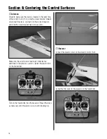
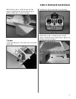
Page 18: ... into position Make sure the aileron servo leads are connected as described in the previous section Center the aileron trim on the transmitter Turn on the transmitter then the receiver Thread the clevis as necessary until the aileron is even with the wing tip Elevator Connect the elevator clevis to the elevator control horn Center the trim lever for the elevator on the transmitter Section 6 Center...

Page 19: ...ecure its location Rudder Connect the rudder clevis to the center hole on the rudder control horn Center the trim lever for the rudder on the transmitter With the radio system on thread the clevis until the rudder is aligned with the fin Slide the clevis retainer onto the clevis to secure its location Section 6 Centering the Control Surfaces ...

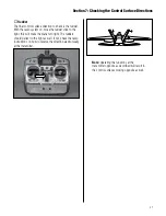
Page 20: ...ot check the radio instructions on how to reverse the direction electronically at the transmitter Elevator With the radio system still on pull back on the elevator control stick to give an up elevator input The elevator should move up from center If not check the radio instructions on how to reverse the direction electronically at the transmitter Section 7 Checking the Control Surface Directions ...

Page 21: ...e plane turn right The rudders should deflect to the right as well If not check the radio instructions on how to reverse the direction electronically at the transmitter Note Operating the functions at the transmitter opposite as described will result in the control surfaces moving opposite as well Section 7 Checking the Control Surface Directions ...

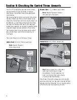
Page 22: ...the low rates for your F 22 Raptor The control throws for your F 22 are as follows Aileron Rate 3 16 in 4 75mm up and down Note Measure the aileron throw at the wing tip 3 16 in 4 75mm 3 16 in 4 75mm Elevator Rate 1 1 2 in 38mm up and down Note Measure the elevator throw at the widest part of the elevator 11 2 in 38mm 11 2 in 38mm Rudder Rate 3 8 in 9 5mm left and right 3 8 in 9 5mm 3 8 in 9 5mm H...

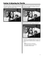
Page 23: ... opening of around 1 16 in 1 5mm Move the throttle stick toward the top of the transmitter The carburetor will now be in the fully open position If the throttle is not operating as described you may need to change the Travel Adjustment setting in the radio To do so read the section in the radio manual on programming the radio Note Once all the radio adjustments are complete remember to turn off bo...

Page 24: ...ge but it can vary up to 1 4 inch 6mm in front or behind the 6 inch mark without causing any problems If your plane is only slightly out of balance try placing the balancing stand towards the nose or tail by this 1 4 inch 6mm and recheck the balance If it looks good and sits level then you re good to go 53 4 in 146mm 61 4 in 158mm 6 in 152mm Lifting the Model and Observations Make sure the F 22 Ra...

Page 25: ...l or the nose of your F 22 Raptor PTS if it does not balance properly Stick on weights available at your local hobby store are the easiest to use and come in sizes that are easily placed on your plane Add just enough weight as necessary to balance your plane Once the weight has been added make sure it is secure and will not fall off in flight Section 10 Balancing Your F 22 Raptor ...

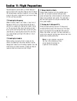
Page 26: ...s and the linkages and surfaces are not binding anywhere Also look at the clevises and clevis retainers to make sure they are secure and will not come loose or fail in flight Range Check the Radio A range check should be part of the preflight process as well The instructions provided with your radio system will detail the correct procedure for checking the range of your particular radio system Thi...

Page 27: ...check the nylon connectors at the servo for any wear or damage If they look worn or in bad shape replace them as well Checking the Control Horns Inspect the control horns to make sure they have not crushed the wood of the control surface If so remove the control horn screws to remove the control horn Place 2 3 drops of thin CA into each of the screw holes In addition use a T pin to poke small hole...

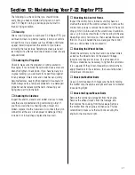
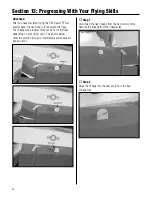
Page 28: ...tions for the flaps depending on your flying skills The photos below show the position for basic intermediate and advanced flap positions Step 1 Disconnect the flap linkage from the flap control horns Remove the linkage from the linkage stay Step 2 Move the linkage into the new position in the flap linkage stay Section 13 Progressing With Your Flying Skills ...

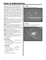
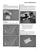
Page 29: ...by for the first few flights The F 22 Raptor PTS will now descend more quickly and land faster like a sport model In the air you can now do a variety of aerobatics such as rolls loops spins and snap rolls Step 1 The droops are held on with clear tape and are taped to the wing using thin double sided tape Pull the tape from the droops to begin the removal process Step 2 Carefully separate the tape ...

Page 30: ...ating correctly Option 1 Use two JR SPORT ST47 JSP20050 servos and two 6 inch Servo Extensions JSP98020 if your radio has programmable mixing You will need to use two separate channels and use your radio to mix them together electronically for this option to work Option 2 Use two JR SPORT ST47 JSP20050 servos two 6 inch extensions and a JR MatchBox or a 6 standard reversing Y harness EXRA320 to li...

Page 31: ... long half servo arm JRPA212 onto the servo and position the servo onto the hatch so the servo arm is centered in the notch Once satisfied mark the location for the servo mounting blocks using a felt tipped pen Note Check to make sure your servo does not hang off one end of the servo hatch If so reposition the servo Having the servo fully on the hatch is more important than having the servo arm ce...

Page 32: ...two end positions of the arm are equal If not reposition the arm as necessary Step 8 Remove the servo and use a 1 16 in 1 5mm drill bit to pre drill the holes for the servo mounting screws marked in the previous step Use the screws supplied with the servo to mount it to the servo mounting blocks Step 9 Pass the servo lead through the flap opening and out of the end of the wing Secure the hatch usi...

Page 33: ...lity while in flight Leading Edge The front of a flying surface Main Landing Gear The wheel and gear assembly the airplane uses to land It is attached to the bottom of the fuselage Nose Gear The part of the landing gear that is attached to the nose of the fuselage The nose gear is usually connected to the rudder servo to help you steer the airplane on the ground Pitch Axis The horizontal plane on ...

Page 34: ...explosive gases such as hydrogen filled balloons or ground mounted devices launching a projectile The only exceptions permitted are rockets flown in accordance with the National Model Rocketry Safety Code or those permanently attached as per JATO use also those items authorized for Air Show Team use as defined by AST Advisory Committee document available from AMA HQ In any case models using rocket...

Page 35: ...o powered model may be flown closer than 25 feet to any person 9 Under no circumstances may a pilot or other person touch a powered model in flight Organized RC Racing Event 10 An RC racing event whether or not an AMA Rule Book event is one in which model aircraft compete in flight over a prescribed course with the objective of finishing the course faster to determine the winner A In every organiz...

Page 36: ... 2007 Horizon Hobby Inc 4105 Fieldstone Road Champaign Illinois 61822 877 504 0233 www horizonhobby com 9890 1 5 ...

Reviews: