


P.O. Box 393
Wadsworth, OH 44282, U.S.A.
Tel: +1 330 336 4550
Fax: +1 330 336 9159
www.hstool.com
OPERATING
RECOMMENDATIONS
for MODEL MFT
Flange Facer
READ THOROUGHLY AND UNDERSTAND THIS PUBLICATION BEFORE
ATTEMPTING TO OPERATE THE EQUIPMENT.
DANGER! The application of this product requires an exposed rotating tool holder and cutting blade. It can
produce HOT, SHARP metal fragments requiring that eye, ear, and hand protection and other protective
clothing be worn at all times. Do not wear loose fitting clothing that may become entangled with the rotating
objects.
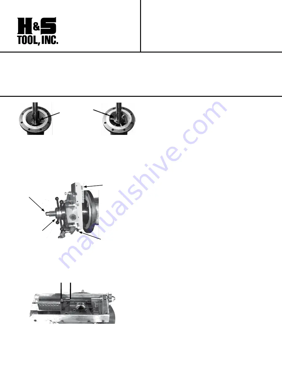
Elbow
Mandrel
Mandrel
Support
Bushing
1. Install the appropriate elbow mandrel in the pipe
I.D. in accordance with the instructions provided with
the mandrel. For accuracy, the elbow mandrel is highly
recommended over the wedge sets. The mandrel
support bushing should also be installed to increase
rigidity and reduce the occurrence of chatter.
Low or High
Range Tool
Holder
Feed Nut
Cap Screw
Ratchet on
Trip Wheel
2. Mount the power unit/flange facer assembly onto the
centershaft by aligning the splines and engaging the
feed nut.
3. Install the low or high range tool holder (depending
upon the flange size) in the tool block.
A
NOTE: Make sure that the distance (A) between the
female slide block and the body is greater that the width
of the flange surface to be machined. Reposition as
necessary. All trip pins must be disengaged.
4. Assure that the area around the machine is clear.
Begin rotating the flange facer and advance the feed nut
until the insert makes contact with the surface. Stop the
machine and note the position of the handles on the
feed nut. Turn the feed nut counter clockwise 1/2 turn to
disengage the insert from the face.
5. Position the insert outside of the flange surface to be
machined by rotating the trip wheel with the ratchet and
socket.
6. Return the insert to the contact depth by turning the
feed nut 1/2 turn clockwise. See specifications below for
approximate adjustment dimensions. Lock the feed nut in
position by tightening the cap screw.
7. Clear the backlash by rotating the trip wheel clockwise
when looking at the nut by hand. Once you feel
resistance, position the next tip of the star wheel so it
points directly at the trip ring (model MFT) or bracket
(model MT). Failure to perform this procedure will result
in damage to the trip pins.
8. Proper adjustment of the gib is necessary for an even
cut and proper timing. The gib is properly adjusted when
there is resistance to turning the trip wheel by hand.
Adjustments are made by turning the gib screw
clockwise to loosen.
9. Engage the desired number of trip pins for the surface
finish required (See specifications below).
10. Allow the machine to run until the flange has been
completely resurfaced.
Specifications
Working
Range: 4.25" I.D. (108.0 mm) to 16.25" (610.0 mm) O.D.
Radial Tool Clearance: 11.0" (279.0 mm)
Radial Feed Rate - .005" (0.13 mm) per pin: All 6 pins .030"
(0.76 mm) Per Revolution Note: Pins must be engaged at
opposing positions for even resurfacing.
Approximate surface finishes are:
1 pin — 63 RMS 3 pins — 125 RMS 6 pins — 500
RMS
Axial Feed Rate: .083" (1.6 mm) Per Full Feed Nut Turn
Approximate Feed Depth Adjustments are:
1/4 turn — .021" (0.38 mm) 1/2 turn — .042" (0.79 mm)
3/4 turn — .063" (1.2 mm)