background image

GB

76

Eldstadsbeklädnad

Rosterreglage

Asklåda

Förbränningsluftsreglage

Brasbegränsare


ANVISNING

26T 26K

installations

Installationsanvisning 

2

Installasjonsanvisning 

25

Installationsanleitung 

49

Installation instruction  73

SE
NO

GB

DE

BAV SE/EX  0601-2 

511299 

Eldningsinstruktion och bruksanvisning för Handöl 20-serien 

2

Heizinstruktionen und Gebrauchsanweisungen für Kaminöfen 
von Handöl 20 

5

Fyringsinstruksjon og bruksanvisning for Handöl 20-serien 

8

Fyringsvejledning og brugsanvisning for Handöl 20-serien 

11

Istruzioni per l’accensione e consigli per l’uso delle stufe-caminetto 
Handöl serie 20 

14

Instructions d’allumage et mode d’emploi de la série Handöl 20 

17

Stookinstructies en gebruiksaanwijzing voor de Handöl 20-serie 

20

Lighting and Maintenance Instructions for Handöl 20 

23

Handöl 20-sarjan lämmitys- ja käyttöohje 

26

SE

DE

NO

DK

IT

FR

NL

GB

FI

HANDÖL

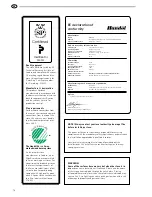
In accordance with standards below
marking was affixed:
European Standard:
SE Quality Certification, P-marked:
NO Standard NS 3059:
DE and AT Standard DIN 18.891 and
Art 15a B-VG:
Type:
Nominal Output:
Fuel:
Minimun draught:
Flue gas temerature:
Energy efficiency:
Emission of CO in cumbustion products:
Distance to cumbustible wall (mm):

Follow the user’s instructions and use only recomended fuel

NIBE AB Box 134 SE-285 23 MARKARYD SWEDEN

2007
EN 13240
Cert no 0112/07
SINTEF 110-0275

RRF-40 07 13 90

Handöl 31/31A/32/32A

5 kW
Wood
12 Pa
280°C
78%
0,14%
Behind 150
Beside 450 
Corner 150

HANDÖL

NIBE AB SE-85 21 Markaryd Sweden

Type:

Production no.

50-series
7090300236

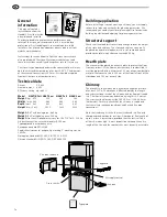
Type plate

Log guard

Fire-box surround

Ash-pan

Grate shuttle

Air supply control

Building application

Before installing a stove or erecting a chimney, you must apply 
to your local planning authority for planning permission. We 
recommend you contact your local planning office for advice on 
building regulations and applying for planning permission.

Structural support

Check that the wood joists are strong enough to bear the weight 
of the stove and chimney. The stove and chimney can usually 
be placed on a normal wooden joist in a self-contained house 
provided the total weight does not exceed 400 kg.

Hearth plate

The stove must be placed on a hearth plate to protect the floor 
from any embers. If the floor under the stove is combustible, it 
must be protected with a minimum of 12 mm of non-combustible 
material that covers at least 300 mm of the floor in front of the 
stove door and 100 mm on each side.

Chimney

The draught in the chimney must generate a negative pressure 
of at least 12 Pa. The draught is affected both by the length 
and cross-sectional area of the chimney, and by how well sealed 
it is. The shortest recommended chimney length is 3.5 metres. 
The cross-sectional area must be 150-200 cm² (140-160 mm 
in diameter). Carefully check that the chimney is sealed and 
that there is no leakage around soot hatches and flue pipe 
connections.

Note that the draught in the chimney is reduced in a flue with 
sharp bends and horizontal sections. A horizontal flue length of 
up to 1 metre is permissible, provided that the vertical flue is 
at least 5 metres high. It must be possible to sweep the entire 
length of the flue and the soot hatches must be easily accessible.

Technical data

Output   

3-9 kW

Nominal output  6 kW
Efficiency rating  up to 80%

Model 

H26T/K Tall H26T Low  H26K Tall  H26K Low 

Weight

 (kg)  470  

420 

240 

240

Width

d (mm)  580 

580 

580 

580

Depth

 (mm)  462 

462 

462 

462

Height

 (mm)  1622 

1312 

1622 

1312

Weight

 H26T with baking oven: 480 kg

Weight

 H26K with baking oven: 265 kg

Weight 

Heat tank (Optional accessory for H26 T/K Tall): 120 kg

Air duct connection, external diameter Ø150 mm.
Type approved in accordance with:
European standard EN-13240
Swedish environmental and quality marking, P-marking cert. no. 
220306
Norwegian standard NS 3059, SINTEF 110-0223 
German standard DIN EN 13240, RRF 4005900

General 

information

This manual contains 
instructions on how the 
Handöl 20 series must be 
assembled and installed. 
In order to be able to guarantee the performance and 
safety of the stove, we recommend that it is installed by a 
professional. Our Handöl agents can recommend suitable 
installers. For information about our agents, please visit our 
website www.handol.se 

Instructions for use and how to light the stove correctly are 
also supplied with the stove. We recommend that you read 
these instructions carefully and keep them safe for future use.

The stove is type approved and must be connected to a chimney 
able to withstand temperatures of at least 350°C. The diameter 
of the external connection is 150 mm. Air should be supplied 
from outside for use as combustion air.

Summary of Contents for H26K Low

Page 1: ...INSTRUCTIONS 26T 26K Installation...

Page 2: ...n approved by a qualified inspector Your local chimney sweep must also be informed about the installation as this will affect the routines for regular chimney sweeping services 378 001 N ORDIC ECOLAB...

Page 3: ...to welcome you to the Hand l family We hope your new stove will give you a great deal of pleasure Your choice of a Hand l stove is testimony to the high standards you demand in terms of quality and de...

Page 4: ...ect the floor from any embers If the floor under the stove is combustible it must be protected with a minimum of 12 mm of non combustible material that covers at least 300 mm of the floor in front of...

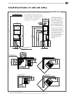
Page 5: ...o upward chimney connection B height from floor to c c rear chimney connection C distance from back to c c upward chimney connection D distance from back to rear chimney connection E distance from bac...

Page 6: ...base plate 288 100 600 890 500 400 300 200 300 400 500 200 Combustible wall Permitted area for combustible material 435 120 8 9 0 810 Combustible wall Fire retardant wall of brick or concrete 365 50 7...

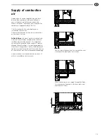
Page 7: ...ustion is approximately 25 m3 hr The illustrations to the right show various installation alternatives The external diameter of the air duct connection on the stove is 64 mm In heated areas the duct m...

Page 8: ...ible hose must be used See illustrations on pages 77 and 78 190 940 780 125 Eldstadsplan 3 2 0 Hearth plate for the Hand l 20 series optional BAV SE EX 0601 2 511299 Eldningsinstruktion och bruksanvis...

Page 9: ...ng from the top the hot air grate must be installed before the chimney Chimney mantle Stop washer Start pipe Rear connection to a masonry chimney Mark out the centre for making a hole in the wall to t...

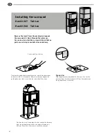
Page 10: ...t the distance from the guide plate up to the rear edge of the door is 445 mm Check that the insert is vertically straight Position the guide plate according to the installation dimensions and ensure...

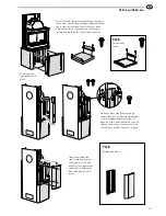
Page 11: ...one at this stage Use the upper outlet on a tall model only if installing a baking oven Otherwise use the lower outlet Assemble the rear side profiles with two screws M6x20 each Check that the profile...

Page 12: ...rows are even and straight so that the tiles do not become misaligned or the gaps between them too large While you are installing the stove make sure that all the stones tiles are level and that each...

Page 13: ...front side profile onto the lower side stone s suspension plate and secure its upper edge with screws in both the insert and side profile Do not tighten the screw in the insert until the second layer...

Page 14: ...side profile Check that it is at the same height as the side stones and then tighten the screws Screw the upper front profiles securely into place in the side stones Press the profile upwards so that...

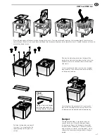
Page 15: ...amper can be opened and closed properly Position the top stones on top of the stove Pins are placed in the soapstone top for the grate to rest on Position the adjusting screws on the top of the back p...

Page 16: ...straight Push in the lower side stones from the front so that their suspension plates hook into the horizontal keyholes of the side profiles Make sure that there is a 5 mm gap between the stone and t...

Page 17: ...th the insert and side profile Do not tighten the screw in the insert until the second layer of side stones are in place Install the two lower front profiles on the lower front stone so that they are...

Page 18: ...mm between the screw flange and the stone Then insert them into the smaller keyholes in the side profiles and check that they are level before finally tightening the screws Hang the middle side stone...

Page 19: ...es securely into place in the side stones Press the profile upwards so that its bent edge is against the lower edge of the side stone Slide the end of the flexible aluminium hoses down into the convec...

Page 20: ...o the upper front stone leaving 4 5 mm between the screw flange and the soapstone Hang the stone into place in the keyholes and allow it to rest against the bent edge of the side profile Check that it...

Page 21: ...n the pins or the cast edge of the tile top Check that the damper can be opened and closed properly Position adjusting screws on the top of the back plate and screw them down so that the screw heads a...

Page 22: ...nd secure it onto the back or top of the oven depending on whether the chimney is to be connected from the rear or directly upwards Hang the stone into place in the keyholes and allow it to rest again...

Page 23: ...ng onto the surface Adjusting screw Position the screen so that it is resting on the corner profiles Slacken the uppermost screws on the corner profiles and fasten the screen into these Screw the conv...

Page 24: ...IAV SE EX 1019 3 811008 Place the base plate of the heat tank on the top of the insert Then place the tank stones as illustrated and push the aluminium hoses through the holes in the tank stone and do...

Page 25: ...den www handol se NIBE Stoves reserves the right to change colours materials dimensions and models at any time without special notice Your dealer can provide you with the latest information The stoves...

Reviews: