


English
English
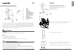
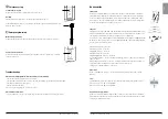
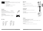
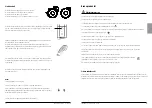
Vega505EE is a mobile patient lift adapted for safe and easy lifting of users weighing up to 230 kg/505 lbs. Vega505EE
features a unique design with a lift arm that can be both raised to an almost upright position and lowered all the way
down to the floor. It is also relatively narrow and compact, with dimensions adapted for use in premises and situations
where space is limited. In spite of the handy size, Vega505EE offers an unusually high lifting height and an extremely
large lifting range. Therefore, the lift can manage all lifting situations and requirements; both low and high lifting, seated or
supine, to and from the floor, bed or chair, and gait training.
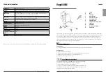
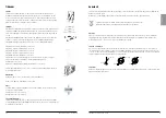
1.
Lift arm
2.
Mast
3.
Handlebar
4.
Emergency stop
5.
Control box / Battery pack
6.
Motor for base-width adjustment
7.
Rear castors with brakes
8.
Sling bar with safety latches
9.
Front castors
10.
Emergency lowering
11.
Motor/actuator for lift arm
12.
Hand control
REVISION HISTORY
REV.
DESCRIPTION
DATE
APPROVED
D
E
F
C
1
2
3
4
B
A
3
2
1
5
C
D
4
6
7
8
A
B
SCALE:1:20
DWG. NO.
REV.
NAME
DATE
DRAWN
APPROVED BY
SHEET 1 OF 1
WEIGHT:
COMMENTS:
STATUS:
TITLE
MATERIAL:
SIZE
Released
Vega505EE
60600003
02
g
2014-09-25
A3
Unless otherwise stated, general
tolerances according to ISO 2768-m
139402makn@z40
This drawing and any information or descriptive matter set out hereon are the confidential and copyright property of Handicare
and must not be disclosed, loaned, copied or used for manufacturing, tendering or any other purpose without their written permission.
Vega505EE
5
1
2
3
5
6
11
10
9
8
7
4
12
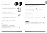
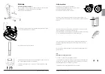
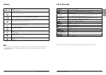
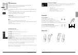
Assembly
Check to ensure that the following components are included
Mast and lift arm, actuator, slingbar, control box, hand control.
Undercarriage with base-width adjustment motor, screws,
washers, nuts and screw covers.
User manual and charger.
Insert the mast onto the base. Assemble according to illustration A and tighten it
hard (65 ± 5 Nm). Loctite. Place the screw covers over the screws.
Place the battery in the mount in the control box.
Connect the cables: The cable for the hand control in outlet HS; the cable for the
hoist motor in outlet M1, and the cable for the base motor in outlet M2.
Release the emergency stop and perform a final inspection (see final inspection).
HS
M1
M2
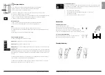
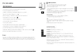
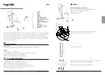
Visual inspection
Inspect lift functions regularly. Check to ensure that material is free from damage.
Before use
Make certain the lift is properly assembled.
Check sling bar connection and safety latch function.
Check lifting function and base-width adjustment.
Check to ensure that the quick-connecting locking pin for the actuator is correctly installed.
Safety information
Always read the user manuals for all assistive devices used during a transfer.
Keep the user manual where it is accessible to users of the product.
Always make sure that you have the right version of the user manual.
The most recent editions of user manuals are available for downloading from our website, www.handicare.com.
Under no circumstances may the lift be used by persons who have not received instruction in the operation of the lift.
It is strongly prohibited to modify the original product.
Always read the user manual
4
5
I N S T R U C T I O N S F O R U S E
I N S T R U C T I O N S F O R U S E


