89
7.2 System adjustment
This session is mainly focused on system adjusting besides compressor. The information here is based on
general type or common situation. Any special design or different case should be reviewed separately with
Hanbell representative
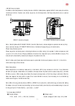
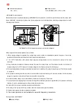
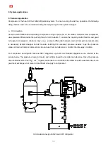
Liquid/Oil injection to chamber
Liquid/Oil injection to chamber is widely used for the controlling of discharge temperature. In the case of using
Liquid/Oil injection to chamber for the discharge temperature control, the Liquid/Oil line should be controlled by a
liquid line solenoid (Normally Closed type). The liquid line solenoid is suggested to be energized when the
discharge temperature reaches 80
℃
(HFC and HFC application). On the Liquid/Oil line, there should be a
regulation valve after the solenoid to adjust the injection flow rate. Before the start-up of compressor, user should
completely close the regulation valve. When the system is running and the discharge temperature exceeds the
set-point, the N.C. solenoid will be energized and user can open the regulation valve gradually to see the variation
of discharge temperature. Try to adjust the regulation valve to the position that the discharge temperature starts to
decrease to the setting point then keep the valve at this position for a while. When the discharge temperature
down to 75
℃
(HFC and HFC application), the liquid line solenoid can be off to stop the injection. Normally the
discharge temperature will start to increase after the stop of Liquid/Oil injection. Therefore, user should observe
the working situation for some time to ensure the proper work of Liquid/Oil injection.
Note: The adjustment of Liquid/Oil injection regulation valve should be executed at all operating conditions,
including partial load.
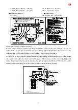
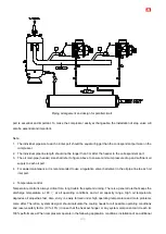
ECO function
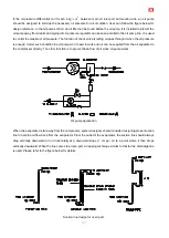
ECO is often used in the refrigeration system to get higher cooling capacity. Compared with using 2 compressors
at a 2-stage compression system, using ECO can save the initial investment and simplify the system design. The
information below should be noted when user applies ECO in the system.
1. There should be a muffler connected to the ECO port directly to absorb the pulsation caused by high speed
refrigerant/gas flow. Sight glass is recommended to be used on the ECO pipe to know whether liquid exists or
not. If liquid refrigerant enters the compression chamber, this will cause damage to screw rotors and bearings.
Accumulator can be used in this line to avoid liquid compression.
2. In a regular start procedure with ECO application, ECO line solenoid (Normal Close Type) should be
energized after the slide valve reaches its minimum ECO working position and should be energized all the
time during the compressor working period. Running compressor without sufficient cooling might cause
severe damage to compressor.
3. Before stop the compressor, the controlling program should unload the slide valve to its initial position
(minimum capacity).
ECO line solenoid should be off when the slide valve position is below minimum ECO
working position.
Summary of Contents for RC2-F Series
Page 6: ...5 2 2 Compressor outline...
Page 7: ...6...
Page 8: ...7...
Page 9: ...8...
Page 10: ...9...
Page 11: ...10...
Page 12: ...11...
Page 13: ...12...
Page 14: ...13...
Page 15: ...14...
Page 16: ...15...
Page 17: ...16...
Page 18: ...17...
Page 19: ...18...
Page 20: ...19...
Page 21: ...20...
Page 22: ...21...
Page 23: ...22...
Page 24: ...23...
Page 25: ...24...
Page 26: ...25...
Page 27: ...26...
Page 85: ...84 Horizontal External Oil Separator OS80 Horizontal External Oil Separator OS100 OS125 OS150...

