


42
Dia.
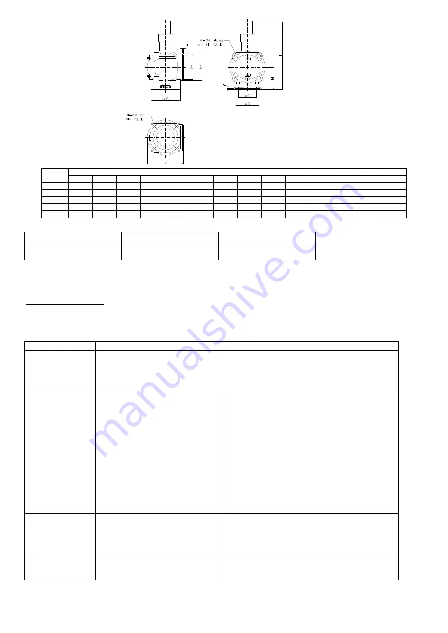
Dimensions unit: mm
A
B
C
D
E
F
G
H
I
J
K
L
M
N
1 1/2”
75
82
40
75
6
5
106
79
262
90
18
105
M16x2
105
2”
90
100
60
91
6
5
122
86
291
131
18
120
M16x2
120
2 1/2
″
110
120
67
111
6
5
137
96
297
152.5
18
140
M16x2
140
3
″
120
135
80
121
6
5
154
107
349
185
22
160
M20x2.5
160
4
″
145
155
105
146
6
5
171
132
406
209
23
185
M20x2.5
185
* Specification of stop valve
Maximum working pressure
Hydrostatic pressure test
Temperature range
28 kg / cm² G
42 kg / cm² G
−
30˚C~150˚C
5. Operation and maintenance
5.1 Compressor start-up
PRE-START CHECKING- Table below shows the required procedures and checkpoints before starting-up the compressor during
commissioning or initial operation of the unit.
Items
Things to be checked
States or standard values
1. Accessories
1.
Oil level
2.
Oil heater
3.
System valves status
4.
Solenoid valves
5.
Capillary
1.
Higher than the middle line of oil level sight glass
2.
Should be kept energizing after compressor shut down.
3.
Opened
4.
Fixed
5.
No serious distortion or damaged
2. Electrical system
1.
Voltage of main power
2.
Voltage of control circuit
3.
Insulation resistance value of the
motor between phase to phase and
phase to ground.
4.
Power terminals and wire cables’
terminals connection.
5.
Grounded
6.
Capacity of electrical accessories
7.
7. Settings of switches, sensors and
controllers.
1.
Electricity voltage should be kept within 5
%
to the
rated voltage, instant maximum voltage drop while
starting should be less than 10% to the rated voltage.
2.
Standard voltage is 220V. Maximum voltage is 230V.
If there is other demand, contact HANBELL.
3.
Insulation resistance value should be above 5M
Ω
.
4.
Power terminals are firmly fixed on terminal block and
well insulated. Keep wire cables away from heat
source and sharpened metal. Power terminals are fixed
firmly and well insulated. Terminal screw and block
are both required.
5.
(Ruled by the local Electricity Regulations.)
6.
Properly selected (or inquired by the system designer.)
7.
Properly set (or inquired by the system designer.)
3. Piping system
1.
Outer piping system
2.
Leakage test
3.
Bolts to fix the compressor.
4.
Vacuum before compressor start.
(Vacuum procedures following p.)
1.
Fixed firmly.
2.
No leakage.
3.
Fix the compressor tightly.
4.
Following EN378-2 and vacuuming compressor are a
must before the system starts.
4. Safety devices
1.
Motor coil sensor (thermistor)
2.
Discharge sensor (thermistor)
3.
Controller
1.
Connected in series with discharge sensor to controller.
2.
Connected in series with motor sensor to controller.
3.
Closed circuit with N.C. & N.O.
Figure 4.9 Dimension of stop valve
Summary of Contents for ExP Series
Page 1: ...1 ...
Page 6: ...6 1 4 ATEX code description II 2 G c IIB T4 II 2 G Ex d IIB T4 Gb ...
Page 8: ...8 RC2 180 ExP A B RC2 200 ExP A ...
Page 9: ...9 RC2 200 ExP B RC2 230 ExP A B UNIT SI mm Imperial in ...
Page 10: ...10 RC2 260 ExP A B SI mm Imperial in UNIT RC2 300 ExP 320 ExP A ...
Page 11: ...11 RC2 300 ExP 320 ExP B RC2 310 ExP A B ...
Page 12: ...12 RC2 340 ExP 370 ExP A RC2 340 ExP 370 ExP B ...
Page 13: ...13 RC2 410 ExP A B RC2 470 ExP A ...
Page 14: ...14 RC2 470 ExP B RC2 510 ExP A B ...
Page 15: ...15 RC2 550 ExP A RC2 550 ExP B ...
Page 16: ...16 RC2 580 ExP A B RC2 620 ExP A B ...
Page 17: ...17 RC2 710 ExP A RC2 710 ExP B ...
Page 18: ...18 RC2 790 ExP A RC2 790 ExP B SI mm Imperial in UNIT ...
Page 19: ...19 RC2 830 ExP A RC2 830 ExP B ...