Subject to change without notice
12
STORAGE MODE ONLY
Additionally,
AUTOSET
automatically selects refresh
mode
(RFR)
when
SINGLE (SGL)
or
ROLL (ROL)
function is in operation.
Automatic CURSOR supported measurement
In contrast to analog mode,
AUTO SET
also causes an
automatic
CURSOR
line setting if time or frequency
measurement has been selected and at least one signal
period is displayed. Neither the signal frequency nor the
pulse duty factor have an effect on the accuracy when
CURSOR
voltage measurement is chosen.
(3)
RM
- The remote control mode can be switched on or
off via the
RS232
interface. In the latter case the “RM”
LED is lit and the electronically selectable controls on
front panel are inactive. This state can be left by
depressing the
AUTO SET
pushbutton provided it was
not inactivated via the interface.
STORAGE MODE ONLY
The
RM
LED is lit during signal transfer via the built in
RS232
interface. At this time the controls are inactive.
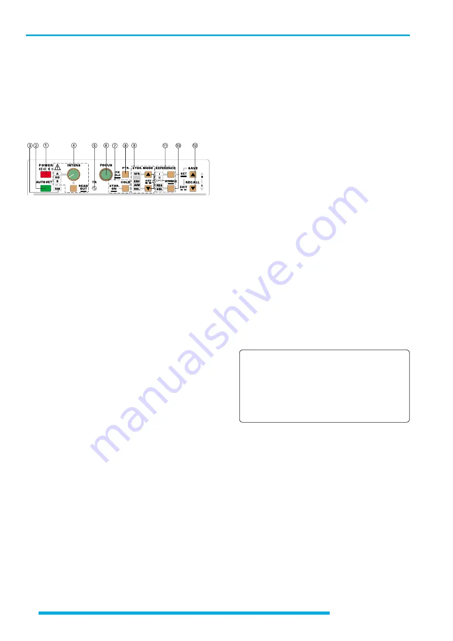
(4)
INTENS
- Knob with associated pushbutton and LEDs.
This control knob is for adjusting both the trace and
readout intensity. Turning this knob clockwise increases
and turning it counterclockwise decreases the intensity
of the selected function (A, RO resp. B).
The
READ OUT
pushbutton below is for selecting the
function in two ways.
Depending on the actual time base mode and the readout
(
RO
) not switched off, briefly pressing the
READ OUT
pushbutton switches over the
INTENS
knob function
indicated by a LED in the sequences:
A - RO - A in condition A time base,
A - RO - B - A if alternate time base mode is present,
B - RO - B in condition B time base,
A - RO - B in XY mode and
A - RO - A in Component Tester (CT) mode.
Pressing and holding the
READ OUT
pushbutton swit-
ches the readout on or off. In readout off condition the
INTENS knob function can consequently not be set to
RO. Briefly pressing the pushbutton causes an error tone
if only A or B time base mode are present. If alternate
time base mode is used the switching sequence is A - B
- A.
Switching the readout off, may be required if interference
distortions are visible on the signal(s). Such distortions
may also originate from the chopper generator if the
instrument is operated in chopped DUAL mode.
In
XY
mode only
A
(for the signal) and
RO
can be
selected unless the readout is switched off. Then just
the A-LED is lit.
The readout is automatically switched off in
COMPO-
NENT TEST
mode and no other LED on the front panel
is lit except A.
All
INTENS
settings are stored after the instrument is
switched off.
The
AUTO SET
function switches the readout on and
selects A time base mode (A-LED lit). The
INTENS
setting for each function is automatically set to the mean
value, if less intensity was previously selected.
(5)
TR
- The trace rotation control can be adjusted with a
small screwdriver (please note “trace rotation TR”)
(6)
FOCUS
- This control knob effects both the trace and
the readout sharpness.
(7)
STOR. ON / HOLD
- Pushbutton with two functions.
STOR. ON
Pressing and holding the pushbutton switches from
analog (
Yt
or
XY
) to storage mode and vice versa. If
CT
(Component Tester) mode is present (only available in
analog mode), it must be switched off first to enable
switching over to storage mode.
The oscilloscope is in analog mode if none of the LED’s
associated with the
STOR.MODE (9)
pushbuttons are
lit and a pre- or post trigger value (
PT...%
) is not indicated
by the readout. Pressing and holding the
STOR. ON
pushbutton switches over to the digital mode, but
without changing the channel operating mode (
CH I, CH
II, DUAL, ADD
and
XY
).
The actual signal capture mode is indicated by one of
the
STOR. MODE-LED‘s
(
RFR - ENV - AVM - ROL
) and
in addition displayed by the readout. In digital
XY
mode
the
RFR
-LED is lit and the readout indicates XY.
If digital
SINGLE
event
(SGL)
capture mode is selected,
all
STOR. MODE
-LED‘s are dark, but the readout displays
the pre- or post trigger value (
PT...%
).
Attention:
The time base ranges are different between ana-
log and storage mode operation depending on
the operating mode!
In ALTernate and B time base mode the B time
coefficient can never be set to a larger value than
the actual A time coefficient. The following
information excludes the X magnifier factor.
Analog mode:
A
time base from 500ms/div to 50ns/div.
B
time base from 20ms/div to 50ns/div.
Storage mode:
A
time base from 100s/div to 100ns/div,
B
time base from 20ms/div to 100ns/div,
This results in the following behavior when switched
from analog to digital mode and vice versa:
1.If in analog mode, the time base has been selected
between 200ns/div and 50ns/div, then on switching
to digital mode the lowest available time coefficient
will be automatically selected, e.g. 100ns/div. If now
one switches back to analog mode without having
made any time base changes in the digital mode, then
the last time base selected in the analog mode is again
active (e.g. 50ns/div).
If on the other hand, the time base is changed after
switching over to digital mode (e.g. to 2µs/div). Then,
Controls and Readout


