


13
Sous réserve de modifications / Reservado el derecho de modificación
1
2
3
4
14 15
8
9
10
11 12 13
7
5
6
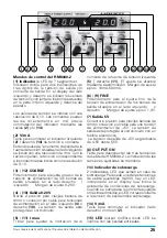
side
(11)
. The adjustment range is between
10mA and 500mA.
(6)
&
(9)
FlNE
Sensitive voltage adjustment knobs vary
the left supply
(6)
and the right supply
(2)
with a 1.4V adjustment range.
(7)
Output 5V
Output terminals for the +5V supply voltage
consists of two 4mm female banana plug
receptacles that connect to wires or male
banana plugs. Electronic circuitry provides
short circuit protection safety. A trimpot
access hole (located above and in-between
the two 5V receptacles) permits a fine
voltage trimming adjustment of between
4.5V and 5.5V.
(8)
OUTPUT ON
DC Output control that simultaneously
activates all three DC outputs (switch
depressed on the HM8040-2. Voltage
displays will show the adjusted output
voltage, even when this switch disconnects
(switch released) the three output voltages.
(13)
Overload indicators
Two individual triangular shaped LED
indicators (left and right) that illuminate
when there is a current overload on one or
both of the two adjustable DC outputs (left
and right).
(14)
V/mA
Display voltage / current selection push
button. See description of
(2)
.
(15)
LED
(DC output enabled)
LED is illuminated when the three DC
outputs are engaged.
(1) Display
Two dual-purpose, 3-digit, 7-Segment
displays provide a selectable readout for
either output voltage or output current. The
left display indicates voltage or current for
the output tterminals on the left side
(4)
and the right display indicates parameters
for the output terminals on the right side
(10)
. Voltages are displayed with 0.1V
resolution and current is in mA when either
button
(2)
or
(14)
is depressed.
(2)
V/mA
Buttons
(2)
(left side display) and
(14)
(right
side) are selection push buttons that
choose either a voltage or current display
individually for each side. Current is
indicated with 1mA resolution when either
button is depressed and voltage is displayed
with 0.1V resolution when either button is
released.
(3)
&
(12)
COARSE
Coarse voltage adjustment knobs vary the
supply voltage setting over the range of 0 -
20V. Knob
(3)
on the left, adjusts the left
supply and knob
(12)
, on the right, adjusts
the right supply.
(4)
&
(10)
Output 0-20V
Output terminals for the 0 - 20V supply
voltages consists of two 4mm female
banana plug receptacles that connect to
wires or male banana plugs. Electronic
circuitry provides short circuit protection
safety.
(5)
&
(11)
Imax.
These are screwdriver access holes for the
current limit adjustment trimpots for the left
side
(5)
and for the right output on the right