18
Bore9 Software
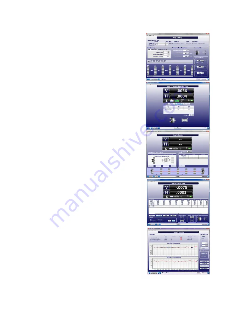
Bore9 features an easy 5-step process, described briefly
below, that guides the user through the alignment process
from setup to results. These results can be plotted, saved, and
exported to an Excel spreadsheet.
Note:
For complete instructions for using the Bore9
Software, refer to Hamar Laser’s Bore9 manual.
•
In
Step 1 – Bore Setup
, the user enters setup information
for the alignment check such as number of bores, distance
between bores, bore diameters and bore straightness
tolerances.
•
In
Step 2 - Target Mounting Error
, an easy procedure is
followed to remove mounting errors. Mounting errors
must be compensated for in order to achieve accurate
results in bore and spindle work. Bore9 uses the
NORMIN method developed by Hamar Laser to quickly
and precisely cancel out these errors and eliminate the
need for complicated, expensive fixtures. The word
NORMIN is a contraction of
NORM
al-
IN
verted, which
briefly describes the method.
•
In
Step 3 – Laser Setup
, on-screen instructions guide the
user through setting up the laser and making it parallel to
reference points.
•
In
Step 4 – Record Data
, bore straightness data is
recorded. There are several different sets of data that can
be taken in this step.
•
In
Step 5 –Results
, results of the recorded data are
plotted on a graph and a least-squares, best-fit data
algorithm is applied to generate the straightness results
and to determine if they are in or out of tolerance. Plot
data can be changed to reflect the position of the
centerline of the bores relative to the end bores, selected
bore numbers, the laser beam or a “Best Fit” line. The
data for each point is recalculated automatically based
upon which references are chosen. Reports are also
generated in this step and can be customized to the four
different bore references. Comments may be added and
the report can be printed with a summary, a graph of the
vertical and horizontal straightness, comments and a table
showing the recorded data.
Summary of Contents for L-708
Page 1: ......
Page 19: ...16 Model R 1307 Readout Control Panel...
Page 20: ...17 Model R 1307C Readout Control Panel...
Page 30: ...27 Figure 20 Sample plot of readout data...
Page 32: ...29...


