32
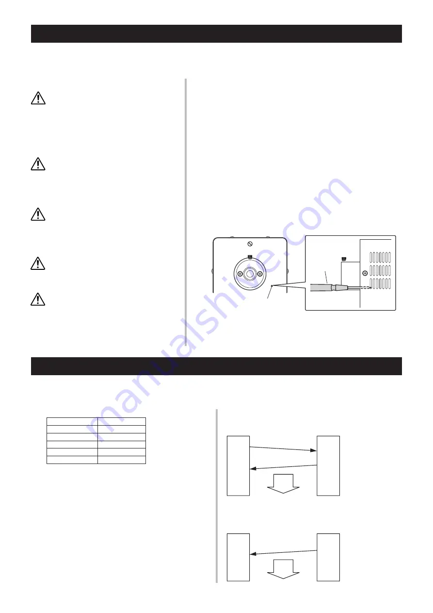
It is possible to control this equipment and make settings through the command (communication) from the computer us-
ing RS232C. To use the personal computer (PC hereunder) with this unit, connect them with the RS232C (cross) cable.
Command Control
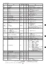
Table 1 : Communication specifications
Baud rate
9600
Parity
None
Stop bit
1
Data bit
8
Flow control
None
Delimiter
CR (0DH)
Without time-out setting, the data division is identified by the
delimiter only.
Communication is executed, in principle, by sending a com-
mand from PC to the unit and returning the result code for
the received command from the unit to PC (Fig. 1).
However, communication is initiated by the unit only when
there is a change in the status (“INP” result code). (Fig. 2)
• Time between reception of command and transmission of result
code: Less than 500 ms
• Time between reception of command and start of lamp and dia-
phragm operation: Less than 50 ms
• Time between reception of command and start of shutter opera-
tion: Less than 25 ms
• Number of command buffers: 20, “ERR” is output when the buf-
fers overflow.
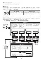
Fig. 1: When PC starts communication
(Except when “ERR05” and “INP**”)
Fig. 2: When this unit starts communication
(Except when “ERR05” and “INP**”)
PC
Command
Light
Source
Unit
Result code
Time
Communication is
started by PC and
finished by the re-
sult code sent from
the unit.
PC
Light
Source
Unit
“ERR05” and “INP**”
result code
Time
Communication
is started by this
unit by sending the
result code.
With an Optical Feedback Unit (option) installed to LIGHTING CURE LC8 Series, it is possible to control light feedback
(automatic control of opening/closing of the diaphragm) of the light source while in the AUTO mode.
Adjustment of Optical Feedback Unit (Option)
■
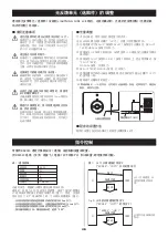
Adjustment of output intensity
q
Turn on the lamp and wait until the lamp stable indicator lamp lights up.
w
Install the output intensity meter (UV meter) to the light guide and make
it ready for measurement.
e
Press the SHIFT and SELECT buttons in the PROGRAM mode to have the output inten-
sity displayed and then open the shutter by pressing the SHUTTER MANUAL button.
r
Keep pressing the UP button for about 3 seconds or until flashing of the
output intensity indicator on the LCD panel stops.
t
Keep pressing the SHIFT and SELECT buttons for 3 seconds or longer to exit the
PROGRAM mode and press the SHUTTER MANUAL button to close the shutter.
y
Press the MANUAL button of the shutter to open the shutter.
u
Using a precision screwdriver, turn the light output adjusting screw so
that the value indicated on the light source agrees with that indicated on
the output intensity meter (UV meter).
i
Continue setting of the output intensity program.
* It is possible to adjust the output intensity even without performing steps
e
to
t
but note that the accuracy in that case would not be as good as when
those steps are performed.
Light output adjusting screw
Precision
screwdriver
(#00)
■
Precautions when using Optical Feedback Unit
For adjustment of the output intensity, be sure to use the
UV meter made by Hamamatsu Photonics.
It may not be possible to set the output intensity with any
other manufacturer’s meter. Also, note that the output in-
tensity value indicated on this unit does not guarantee the
absolute value. This is why it is necessary to check the
output intensity using the UV meter made by Hamamatsu
Photonics during the before work inspection.
Be watchful for dirt on the light guide.
If the end of the light guide for light output becomes dirty
after adjusting the output intensity, the output intensity as
set in advance may not be obtained. Also, such dirt may
hinder proper output intensity adjustment and lead to a
faulty feedback setting.
Output intensity setting must not exceed the maximum
output intensity level.
The output intensity of the lamp is deteriorated as the op-
eration time increases. Note that when the output intensity
is set to a higher level, a faulty optical feedback setting may
occur even within the guaranteed service life of the lamp.
Use a #00 precision screwdriver when adjusting the
output intensity adjusting screw. The output intensity ad-
justing screw is located about 15 mm inside of the frame
surface. Be very careful when inserting the screwdriver.
Make sure that the light guide is installed securely before
adjusting the output intensity. Without the light guide be-
ing installed properly, it is not possible to adjust the output
intensity correctly. Also opening the shutter when the light
guide is not installed may cause strong ultraviolet rays to
be emitted, possibly resulting in a damage to eyesight.
■
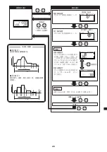
Program setting method
Use the same program setting method and operation procedure in the
AUTO mode as those described in pages 30, 31.
Summary of Contents for LIGHTINGCURE LC8
Page 2: ...2...
Page 6: ...6 1 1 1 2 JIS C 7550 3 JIS T 8141 30 kV 15 1 MPa 10 4 MPa 40...
Page 8: ...8 25 80 10 cm 10 cm L9566 L9588 10 cm 10 cm 10 cm 10 cm...
Page 11: ...11 q OFF w e 1 MPa 10 r t y u...
Page 35: ...35 1 1 1 2 IEC 2006 IEC 62471 EMI 30kV 15 1MPa 10 4MPa 40...
Page 37: ...37 L9566 L9588 10cm 10cm 10cm 10cm 25 80 10cm 10cm...
Page 40: ...40 q OFF w e r t y 1MPa 10 u...
Page 54: ...54...
Page 55: ...55...


