


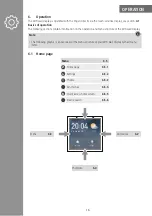


SeTuP
8
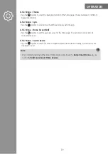
Then mount the bracket of the WiFi wall displayat the intended mounting location:
•
Place the bracket in front of the flush-mounted box from which the wires come.
•
Connect the neutral conductor and the phase conductor to the N and L sockets on the bracket as
shown below.
•
If necessary, provide an existing protective earth conductor with a terminal. The protective earth con-
ductor remains in the flush-mounted box.
Input:10
0 V~240
V AC
50/60 H
z
Hama G
mbH &
Co KG
86652
Monheim
German
y
2
2
•
Mount the bracket on the slotted holes with the screws supplied
2
.
•
Carefully place the WiFi wall display on the bracket.
The WiFi wall display audibly clicks into place.
•
Switch on the relevant fuse (fuse box) for the room in which you wish to install the WiFi retrofit switch.
•
The WiFi wall display switches on automatically. After a short wait, you will hear a confirmation tone.
•
Continue with the initial set-up, see Chapter
5.2 Initial setup of the WiFi wall display
Phase conductor (L)
Neutral conductor (N)


