background image

6.3.2 Opening the front panel

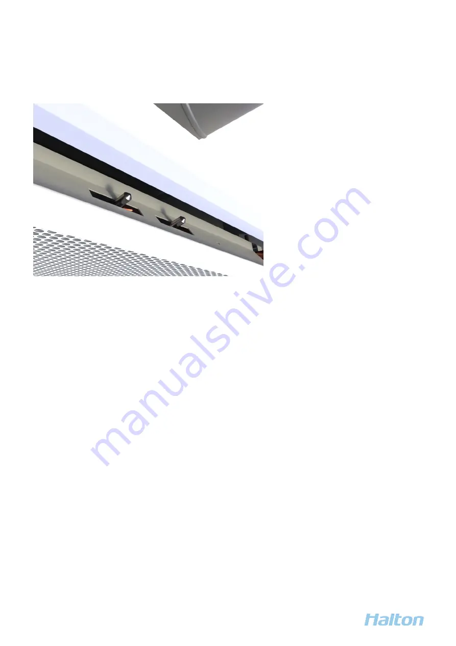
The latches for opening the front panel are located at both ends of the front panel.

Figure 15. Front panel latches

To open the front panel, press the latches towards each other.

6.3.3 Filling in the maintenance documents

Fill in the maintenance documents required by your organisation.

6.4 Checks after maintenance

Make sure you have filled in the maintenance documents.

Halton Rex Expander (RXP) - Installation, commissioning, and maintenance guide

23

1.0

All rights reserved ©Halton

Summary of Contents for Rex Expander

Page 1: ...Halton Rex Expander RXP Installation commissioning and maintenance guide Enabling Wellbeing All rights reserved Halton...

Page 2: ...nstallation 14 4 1 Before you start 14 4 1 1 Safety during installation 14 4 1 2 Installation process 14 4 1 3 Installation requirements 15 4 1 4 Checks before installation 16 4 2 Step by step instruc...

Page 3: ...3 Filling in the maintenance documents 23 6 4 Checks after maintenance 23 7 End of life 24 7 1 Removing the product from use 24 7 2 Recycling and waste disposal 24 8 Troubleshooting and repairs 26 8...

Page 4: ...ny permitted use of the information included herein is at your own risk Halton may amend or replace the information included in this document at its sole discretion without further notice and liabilit...

Page 5: ...over 20 kg 44 lbs alone Use a lift or seek assistance CAUTION PERSONAL INJURY HAZARD Follow all local health and safety regulations and use proper personal protective equipment Notices NOTICE NOTICE A...

Page 6: ...Quality HAQ control Throw pattern expanded to corners which ensures pleasant room conditions even with high cooling capacities 2 2 Operating principle The primary supply air enters the plenum of the...

Page 7: ...space In normal conditions fresh supply air is provided through the nozzles Whenever additional air is needed boost VAV function the HAQ control opens and provides more air VAV stands for Variable Ai...

Page 8: ...Supply air from nozzles and HAQ control boost mode Figure 5 Manual actuator of HAQ control Figure 6 Electric actuator of HAQ control Halton Rex Expander RXP Installation commissioning and maintenance...

Page 9: ...2 3 Structure and materials Figure 7 Halton Rex Expander parts Halton Rex Expander RXP Installation commissioning and maintenance guide 9 1 0 All rights reserved Halton...

Page 10: ...r galvanised steel 5 Plenum Pre painted galvanised steel Polyester painted white RAL 9003 6 Brackets Galvanised steel 7 Spigot Galvanised steel 8 Frame Pre painted galvanised steel Polyester painted w...

Page 11: ...ions RXP 600 Figure 9 Halton Rex Expander dimensions RXP 1200 Weight Product AQ model Dry mass excl water kg Water volume l RXP 600 NA 10 5 0 5 MA 11 4 MO 11 6 RXP 1200 NA 20 9 1 2 MA 21 8 MO 22 1 Hal...

Page 12: ...te in separate shipments 3 2 1 Handling the product To protect the product from damage or dirt keep the product in its original box until it is needed for installation There is a product label in each...

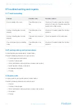
Page 13: ...lation inside the plastic wrappings It is a strict requirement that the products be stored in a dry indoor environment Products must be protected against moisture in any junction box or other closed e...

Page 14: ...and safety regulations and use proper personal protective equipment NOTICE NOTICE All installation commissioning and maintenance work must only be carried out by qualified personnel NOTICE NOTICE All...

Page 15: ...the middle of the left side of the unit The Halton Rex Expander chilled beam can be attached directly to the ceiling surface H 220 mm or suspended using threaded drop rods 8 mm The brackets for ceilin...

Page 16: ...e the unit is in good condition 2 From the design drawings determine the installation place 3 From the design drawings determine the orientation of the unit the locations of the water circuit connecti...

Page 17: ...ttings be careful not to damage the pipes Connect the water circuit connections according to the design drawings You can use for example push fit fittings or compression fittings With compression fitt...

Page 18: ...is connected to the ductwork correctly The water connections are connected correctly Note The visible surface of the unit is protected with removable plastic coating It protects the surface from dust...

Page 19: ...ded minimum inlet water temperature of the heat exchanger is 14 16 C Balancing and control of water flow rates The water mass flow rates of the Halton Rex Expander chilled beam are balanced with adjus...

Page 20: ...1 2 6 3 5 5 3 2 2 2 2 7 3 6 3 1 4 0 5 8 3 2 7 3 2 4 1 3 7 4 5 6 3 4 3 2 3 7 4 6 4 1 5 0 6 8 5 3 7 4 1 5 1 4 6 5 5 7 3 6 4 1 4 6 5 5 5 0 5 9 7 7 7 4 5 5 0 5 9 5 5 6 3 8 1 8 4 9 5 4 6 3 5 9 6 7 8 5 9 5...

Page 21: ...y default the manual actuator of HAQ control is closed Adjust the position of the manual actuator of HAQ control according to the HVAC plan of the building Figure 14 Manual actuator of HAQ control Hal...

Page 22: ...removable to allow general maintenance and cleaning 6 2 Maintenance schedule Carry out scheduled maintenance according to the maintenance plan of the building 6 3 Step by step instructions 6 3 1 Clean...

Page 23: ...the front panel press the latches towards each other 6 3 3 Filling in the maintenance documents Fill in the maintenance documents required by your organisation 6 4 Checks after maintenance Make sure...

Page 24: ...osed of in conformity with existing local regulations Polyethylene outer protective film Cardboard angle protections cardboard boxes etc Wood pallet plywood etc Electronic and other components Any ele...

Page 25: ...ccordance with steel recycling provisions If you require more details for recycling and waste disposal concerning a product contact Halton Halton Rex Expander RXP Installation commissioning and mainte...

Page 26: ...flow rate is too high Check and if needed adjust the chamber pressure 8 2 Fault reporting and reclamations For fault reporting and reclamations contact Halton Provide the following information for eas...

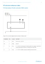
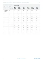
Page 27: ...ent G 1 Red 24 V AC 24 48 V DC G0 2 Black Ground Y 8 Grey 0 10 V DC Control signal in for HAQ position The voltage corresponds to the HAQ openings and k factors according to the table below U 9 Pink 0...

Page 28: ...9 4 7 1 2 1 7 2 1 3 1 2 6 3 5 5 3 2 3 2 2 2 7 3 6 3 1 4 0 5 8 3 4 2 7 3 2 4 1 3 7 4 5 6 3 4 5 3 2 3 7 4 6 4 1 5 0 6 8 5 6 3 7 4 1 5 1 4 6 5 5 7 3 6 7 4 1 4 6 5 5 5 0 5 9 7 7 7 8 4 5 5 0 5 9 5 5 6 3 8...

Reviews: