


5
Capture Ray
TM
Operation & Maintenance & Service Manual
CJUV/0
120
09/re
v1/EN
METHOD OF OPERATION
Capture Ray
TM
hood systems operate properly when the KSA grease extractors and backup mech fil-
ters are properly installed, the UVC lamps are clean and the exhaust fan is turned on.
The system is engineered to reduce maintenance and keep service issues to a minimum. The unit is
constructed of stainless steel with removable KSA grease extractors and GPS filters for interior inspec-
tion and cleaning.
Make-up Air Supply
Make-up air must be provided to replace the air exhausted through all kitchen exhaust systems. The
“make-up air” may be supplied through a front face discharge plenum on the Capture Ray
TM
hoods or
from registers in the kitchen area. Velocities of “make-up air” should be kept to a minimum especially
near the exhaust hood perimeter.
> CAUTION:
High “make-up air” velocities will distrub smoke capture. Many codes call for a number of
air changes per hour. This should be reviewed with the entire ventilation requirements of the facility.
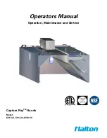
METHOD OF DETERMINING AIRFLOWS
The air flow through the Capture RayTM hoods in determined by using the testing and balancing
(T.A.B.) port as showin in figure 3.
T.A.B.
TM
- TESTING AND BALANCING PORTS
Ps
s
P
The capture-jet and exhaust air flows are easily and accurately
determined by matching the pressure difference from the
T.A.B. ports mounted in each plenum. Corresponding air
flows, in cfm per foot of hood, can be read from the diagrams
provided in this catalog.
0.5
0.7
0.9
1.1
1.3
1.5
1.7
1.9
2.1
150
170
190
210
230
250
270
290
Airflow (cfm/ft)
(based on heat load design)
dP
m
(i
nc
he
s
W
C
)
Capture-Ray Hood Example
Measured Pressure
∆
P
s
= 1.4"
CFM/ft = 238