12
Capture Jet
®
Operation & Maintenance Manual
OM-0
05/0520
17/re
v3/EN
Capture Jet
®
Fan Installation
Typical Wiring of External
Capture Jet
®
Fan
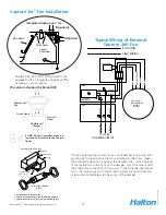
Models KVE, KVC, KVR, KVW and KCH are
equipped with an Integrated Capture Jet
®
fan
package, as shown above.
T.A.B. Ports
KSA Filter
Integrated Capture Jet
®
fan
(Optional)
(Standard)
Speed
Controller
5 AMP Speed Controller wired on
top of hood or located in the Control
Panel
Capture Jet
®
Plenum
Capture Jet
®
Fan
Top of Hood
Front of
Hood
BLOWER MOTOR
CAPTURE JET
120/60/1
1.3 AMPS
BR
OWN
GREEN/L
T GREEN
BL
UE
BLA
CK
SPEED
RED
RED
CAPACITOR
GREEN
CONTROLLER
BLA
CK
GREEN
WHITE
120 V
HO
T
GR
OUND
NEUTR
AL
INCOMING CIRCUIT
120/1/60
J BOX
J BOX
BLACK
WHITE
BY HALTON
FIELD WIRING
The KVL external Capture Jet fan has a fire damper in the collar that
must be set to open before the fan is attached to the collar. Open
the damper blade until it is against the damper stop. Hook one end
of the fusible link to the hook on the damper. Hook the other end of
the fusible link to the hook on the collar. If attaching the Capture Jet
fan to the intake collar with sheet metal screws be certain that the
screws do not interfere with the action of the damper.
DAMPER
DAMPER STOP
COLLAR
FUSIBLE LINK
74° C (165° F)
CUTAWAY VIEW OF COLLAR
FUSIBLE LINK ASSEMBLY
DETAIL
1. OPEN DAMPER TO DAMPER STOP
2. HOOK ONE END OF FUSIBLE LINK TO HOOK ON DAMPER
3. HOOK OTHER END OF FUSIBLE LINK TO HOOK ON COLLAR
This style is standard for Model KVL

