background image


Instruction Manual HIPERDRIVE with EtherCAT 

25 

 
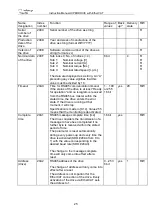
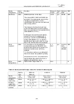
Name, 
designation


Index 
number


Function


Range of 
values


Back
up?


Delivery 
state


R/W


Serial 
number of 
the drive


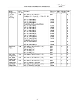
209C


Serial number of the drive as string


R


Production 
date of the 
drive


209D


Year and week of manufacture of the 
drive as string (format WW/YYYY)


R


Version of 
the drive


209E


Software version number of the drive as 
string (format x.xx)


R


Nominal data 
of the drive


209F


Sub index 0: No. of indices (= 4)


8 bit


R


Sub 1: 
Sub 2: 
Sub 3: 
Sub 4:


Nominal voltage [V] 
Nominal current [A] 
Nominal torque [Nm] 
Nominal rated speed [r.p.m.]


The data are displayed as a string. 

An “A” 

preceding any value signifies that this 
value must be divided by 10.


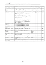
Timeout


20A0


Time for RS485 communication timeout 
If the status of 

the drive is at least “Ready 

for operation” and no telegram is received 
from the RS485 bus master within the 
stated time, the drive enters the error 
state. If the drive is running at that 
moment, it will stop.


Specification is made in [0.1s]. Value 255 
means that the monitoring is deactivated.


1… 100 
or 255 
16 bit


yes


20 

R/W


Complete 
time


20A1


RS485 message complete time [ms] 
The drive considers the transmission of a 
message to have been completed if no 
further byte is received within the stated 
period of time. 
The parameter is reset automatically 
during every power-up and every time the 
drive is activated (SDO #20A4 from 0 to 
1) with the value corresponding to the 
desired baud rate (SDO #20A3). 
 
The change to the message complete 
time will only come into effect after a 
reset.


16 bit


yes


R/W


Address 
(drive)


20A2


RS485 address of the drive 
 
The change of address will only come into 
effect after a reset. 
The address is not important for the 
EtherCAT connection of the drive. Every 
activation of the drive via EtherCAT sets 
the address to 1.


0…253 
8 bit


yes


R/W


Summary of Contents for HIPERDRIVE

Page 1: ...8 Instruction Manual HIPERDRIVE with EtherCAT halstrup walcher GmbH Stegener Stra e 10 D 79199 Kirchzarten Germany Tel 49 0 76 61 39 63 0 Fax 49 0 76 61 39 63 99 E Mail info halstrup walcher de Intern...

Page 2: ...Setting the device address 13 4 4 LEDs for the HIPERDRIVE bus adapter 14 4 5 Meaning of the LED statuses of LED RS485 15 4 6 Start up HIPERDRIVE bus adapter 15 5 The EtherCAT interface 16 5 1 EtherCAT...

Page 3: ...Instruction Manual HIPERDRIVE with EtherCAT 3 8 Technical data 36 8 1 HIPERDRIVE Hub 36 8 2 Drives with HIPERDRIVE bus adapter 37 9 Certificate of Conformity 39...

Page 4: ...ces It must be provided to any individuals who assume responsibility for operating the device at a later date It must include any supplementary materials provided by the manufacturer The manufacturer...

Page 5: ...d start up Assembly and the electrical connections should only be handled by professionals They should be given proper training and be authorised by the operator of the facility The device may only be...

Page 6: ...s system simplifies the wiring The positioning system is especially suitable for automatically setting tools stops or spindles for wood processing equipment packing lines printing equipment filling un...

Page 7: ...ound control unit 4 NC 5 NC Supply for the drives connected to the HIPERDRIVE Hub The motor power supply 24VDC and GND is connected using two screw connections for cable lugs M6 These are concealed un...

Page 8: ...our wire cables should be used 3 2 Setting the device address The device address is assigned via the bus of the EtherCAT master Alternatively the configured station alias can be defined using the two...

Page 9: ...collective message Switch S3 0 Status of the RS485 connection to the motor selected with S3 see also following section Meaning of the rotary switches and keys S1 S2 Definition of the configured statio...

Page 10: ...is not marked as required No drive errors for any non required drive flashes red green simultaneously 2 Hz All drives marked as required are functioning without communication or drive errors At least...

Page 11: ...ion the hub loads the most recently saved information about the ports at which drives were most recently required i e were released for issuing run commands If at least one drive requested recently is...

Page 12: ...radial tolerances To prevent damage to electromechanical components please avoid banging or knocking the output shaft 4 2 Pin assignment HIPERDRIVE bus adapter A 4 pin screw terminal for connecting th...

Page 13: ...igh In addition the two GND potentials should be connected outside the device e g directly at the power supplys which provide the two supply voltages so that potential compensating currents will not f...

Page 14: ...ach of the ports P1 P2 has an associated green LED for the Link and Activity states For each port the following states are possible off no connection on line connection is active no data activity flic...

Page 15: ...to the drive if this is marked as required red green on Drive error communication to the drive is functioning correctly flashes green 2 Hz The drive is not marked as required no drive error flashes re...

Page 16: ...P2 has an associated green LED for the Link and Activity states For each port the following states are possible off no line connection flickering at 10 Hz line connection data transmission active on...

Page 17: ...ntity 1018 Sub index 0 No of indices 4 Sub 1 Vendor ID 0x000002D8 Sub 2 Product code Sub 3 Revision number 0x00010000 Sub 4 Serial number 8 bit 32 bit 32 bit 32 bit 32 bit 4 R R R R R Receive PDO 1 ma...

Page 18: ...22060020 In addition for Hub 8 Sub 13 0x22840010 Sub 24 0x24060032 8 bit 32 bit 32 bit 32 bit 32 bit 32 bit 32 bit 32 bit 32 bit 32 bit 32 bit 32 bit 32 bit 32 bit 32 bit R R R R R R R R R R R R R R R...

Page 19: ...the SII by the master i e not via SDO it will be saved automatically by the HIPERDRIVE Hub or adapter 16 bit yes 0 R W HIPERDRIVE category 2002 Adapter HIPERDRIVE SINGLE 4 port hub HIPERDRIVE HUB 4 8...

Page 20: ...ets the values of all the parameters that can be saved in the hub or adapter to the last values saved by the user without saving the parameters in EEPROM Writing a 1 sets the values of all the paramet...

Page 21: ...0 R W Percentaged target speed 2081 Sets the speed r p m as a of the max value SDO 208C 1 100 8 bit no 100 R W Percentaged maximum torque 2082 Sets the torque as of the maximum value Internally the v...

Page 22: ...no valid response from the drive Number of faults 2089 Number of faults that have occurred since the last clearing of the fault buffer or since the last activation of the axle Setting to 0 clears the...

Page 23: ...internal measuring system to the physical conditions Resetting has no effect Setting to the delivery state sets the value to 0 the new actual position then corresponds to the position of the output sh...

Page 24: ...aling 2095 Scaling of the position Sub index 0 No of indices 2 Sub 1 Numerator value Sub 2 Denominator value 8 bit 16 bit 16 bit yes yes 2 256 1 R R W R W Speed scaling 2096 Scaling of speed r p m Sub...

Page 25: ...elegram is received from the RS485 bus master within the stated time the drive enters the error state If the drive is running at that moment it will stop Specification is made in 0 1s Value 255 means...

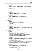
Page 26: ...drive is not accepting run commands issued via EtherCAT the actual values status word actual r p m and actual position are not being updated 1 The drive can be run via EtherCAT the actual values are...

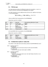
Page 27: ...31 3 Percentaged maximum torque 2082h 32 63 4 7 Target position 2083h 2 Transmit PDO from the perspective of the HIPERDRIVE Assignment cannot be modified Bit Byte Meaning Corresponding SDO index numb...

Page 28: ...t in the case of a negative edge of bit 7 of the control word in the state Fault This bit is reset in the case of a negative edge of bit 0 of the control word Bit 7 Warning This bit is set when an err...

Page 29: ...the state Ready for operation a new movement will only be started if bit 6 of the control word complements the bit acknowledgement of target value in the status word toggle function Bit 13 Drive at s...

Page 30: ...command is continued when bit 5 is set once again Function in speed control mode Endless When this bit is set the movement in speed control mode is endless otherwise until it reaches the respective en...

Page 31: ...o Switch on Bit 11 Start referencing Reserved must be set to 0 Bit 12 Speed control mode If this bit is set and the drive is in the state Operation enabled an edge of bit 6 triggers a run in speed con...

Page 32: ...status word The requirement for each run is that the percentaged target speed and percentaged maximum torque have a value 0 In addition for a run command the target position must be set to a permitted...

Page 33: ...I 1 increment and direction default 1 16 rotation Jog key S4 Jog counter clockwise Jog key S5 Jog clockwise SI 2 Sets the speed r p m as a of the max value from SDO 208C SI 3 Sets the torque as a of t...

Page 34: ...enters the state Fault An entry is then made in the fault buffer SDO 2088 on drive 1 The fault must be acknowledged by a negative edge to bit 7 of the control word The drive then enters the state Swi...

Page 35: ...2 mm 1 10 mm 20 256 7 5 Aborted run when the master fails If the connection to the master is interrupted during a positioning run the master cannot abort a run that is already underway In order to gen...

Page 36: ...on class IP 65 Duty cycle 100 Electrical data Supply voltage 24 VDC 15 Recommendation Use a regulated power adapter Nominal current control unit 0 15 A Motor connections One 6 pin screw terminal per m...

Page 37: ...ical data Nominal power output HDA 30 30 W HDA 45 45 W HDA 70 42 W Supply voltage 24 VDC 15 Recommendation Use a regulated power supply Nominal current HDA 30 3 5 A HDA 45 4 8 A HDA 70 4 8 A Connectio...

Page 38: ...ather key type H 12 mm hollow shaft Maximum radial force linear type 200 N radial type 440 N Maximum axial force linear type 150 N radial type 165 N Dimensions l x w x h see drawings Weight approx HDA...

Page 39: ...Instruction Manual HIPERDRIVE with EtherCAT 39 9 Certificate of Conformity 7100 004854D_Hiperdrive_ECAT doc 07 2018 Re...

Reviews:

Related manuals for HIPERDRIVE