Supplied By www.heating spares.co Tel. 0161 620 6677
25
32
MUL
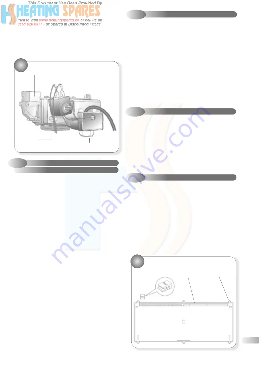
TIFUNCTIONAL GAS CONTROL
Gas outlet flange
Modureg
Electrical lead
DHW Burner
pressure adjuster
Burner pressure
test point
Inlet pressure
test point
Gas service cock
•
•
•
•
•
•
•
9.5.2
GAS CONTROL BURNER PRESSURE
SETTING PROCEDURE
Refer to Figs. 32
a)
Connect a suitable manometer to the bur
ner pressure test
point. Turn on the gas supply.
Check for gas tightness taking the precautions described in
section 5 and re-commission the appliance in accordance with
section 5.3.
Note:
It is only possible to set the DHW heat inputs because the
CH heat inputs are electronically set by the control.
A 2mm and 3mm Allen key ar
e required for this adjustment.
a)
T
urn the DHW temperature control knob fully clock-wise to the
Comfort position and fully open any DHW tap to ensure that
the boiler fires at full rate.
b)
Remove the cap fr
om the pressure adjuster and insert the Allen key.
c)
T
urn the small diameter shaft clockwise to increase, or anti-
clockwise to decrease the burner pressure. Set to 15.5 mbar
(6.2 in wg) Nat. Gas, 23.4 mbar (9.4 in wg) Propane.
d)
Disconnect one of the low voltage electrical leads fr
om the
Modureg to reduce the rate to minimum.
e)
T
urn the large diameter shaft clockwise to increase, or
anti-clockwise to decrease the burner pressure. Set to 1.0
mbar (0.4 in wg) Nat. Gas, 2.3 mbar 0.92 in wg Propane.
f)
Reconnect the Modur
eg lead and replace the adjuster cap.
g)
Close the DHW tap and ensur
e that the burner is
extinguished and the pump stops after a brief overrun
period. Remove the pressure gauge and tighten pressure
test point screw, open the DHW tap to re-light the burner
and test for gas tightness screw.
h)
Close the DHW tap, r
e-assemble in reverse order and ensure the
plastic cap is refitted and a blob of paint re-applied to seal it.
9.6
AIR PRESSURE SWITCH
Refer to Fig. 29
a)
Ensur
e supply voltage is isolated.
b)
Remove the casing fr
ont panel and sealed chamber front
panel. Refer to section 9.3.
c)
Disconnect the sensing pipes fr
om the pressure switch.
Note that the short pipe from the flue gas sampling point is
connected to the rear (-ve) connection on the pressure switch.
d)
Disconnect the electrical leads fr
om the pressure switch, noting
their positions.
e)
Remove the two securing scr
ews and withdraw the switch from
the boiler.
f)
Fit the new pr
essure switch and re-assemble in reverse order,
referring to the wiring diagrams (section 7) if necessary.
9.7
DIVERTER VALVE ACTUATOR
Refer to Fig. 33
a)
Ensur
e supply voltage is isolated.
b)
Remove the casing fr
ont panel and lower the controls fascia
panel. Refer to section 9.3.
c)
Unplug the electrical lead fr
om the actuator.
d)
W
ithdraw the retaining clip to release the actuator from the
head of the diverter valve.
e)
Fit the new actuator and r
e-assemble in reverse order.
9.8
PCB
Refer to Fig. 29 and 33
a)
Ensur
e supply voltage is isolated.
b)
Lower the contr
ols front panel and lower the control fascia
panel. Refer to section 9.3.
c)
Unplug the electrical leads fr
om the PCB. Refer to section 7.
d)
Remove the PCB plastic cover
.
e)
Unclip the PCB and withdraw
.
f)
Car
efully remove the three control knobs, noting their position
and fit onto new PCB.
g)
Fit the new PCB and r
e-assemble in reverse order. Ensuring
control knobs are free to move and reset button operates.
33
PCB HOUSING
NG/Pr
opane
chip card
Electrical
Connectors
Securing
Screws
•
•
e)
Disconnect the two electrical leads fr
om the Modureg.
f)
Ensur
e that the gas supply is turned OFF and remove the four
socket screws securing the gas service cock to the gas control.
g)
Remove the four scr
ews securing the gas outlet flange to
the gas control.
h)
W
ithdraw the gas control from the boiler.
i)
Fit the new contr
ol and re-assemble in reverse order, ensuring
that the ‘O’ rings are correctly fitted.


