


91
Page
91
SmartFOAM
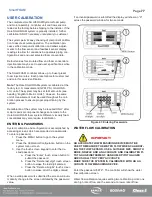
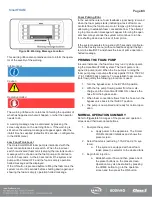
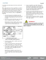
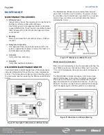
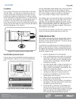
Resetting Maintenance Interval Due Dates
Maintenance intervals are reset by entering the password
“9999” in the password entry screen (Calibration/Configura-
tion button in the main menu) and then the SmartFOAM con-
troller will show the maintenance minder screen with the
maintenance reset icons present. Touch the Maintenance
Reset icon next to the maintenance interval desired and the
date will be updated.
Figure 79: Maintenance Reset Icons
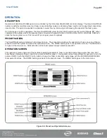
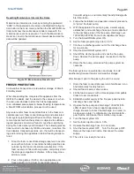
FREEZE PROTECTION
Cold weather transport and cold weather storage of Smart-
FOAM systems:
When transporting the completed fire apparatus from the
OEM to the dealer, and the dealer to the end-user, or, when
the end- user decides to store the finished apparatus
in an unheated area subject to below freezing temperatures,
a SmartFOAM winterization process must be used.
Any water and/or foam concentrate that is in the foam con-
centrate reservoir, foam concentrate pump, and associated
foam system piping/tubing will freeze and then break sys-
tem components when the system is subjected to subfreez-
ing temperatures commonly found in over-the-road driving
during fire truck delivery and transport. The following precau-
tions must also be taken by OEMs, end-users, re-sellers, fire
truck dealers, transport agencies, etc., that will be transport-
ing and/or storing the apparatus in below freezing tempera-
tures:
1. Drain the foam concentrate storage reservoir in accord-
ance with safe foam concentrate handling practices as
outlined by the foam concentrate manufacturer. If the
foam reservoir is filled with only water, completely drain
the storage compartment of water. After empty, close
all drain valves.
2. Pour in five gallons (18.93L) of an appropriate anti-
freeze solution in the foam concentrate reservoir.
Consider using an environmentally friendly biodegrada-
ble formulation.
3. Follow the Installation and operation manual procedure
to “prime” the foam pump.
4. With the apparatus fire pump in gear, a water supply
established, and a discharge hose and nozzle attached
to the discharge side of the fire pump, discharge over
100 GPM (380 LPM) from a foam capable discharge.
5. Turn the SmartFOAM system ON.
6. Set the foam proportioning rate to 3.0%.
7. Continue to discharge water out of the discharge hose
for one-minute.
8. Shut the SmartFOAM system OFF.
9. Shut off the discharge valve and shut the fire pump
down. Remove the water supply connection to the fire
pump.
10. Drain the fire pump, valves and fire pump system ac-
cessories.
The foam system is now winterized and ready for cold
weather duty transport and/or cold weather storage.
After transport, prior to the placing the unit in service:
1. Drain the foam concentrate reservoir of antifreeze in an
environmentally friendly fashion.
2. Shut all foam reservoir drain valves.
3. Fill the foam reservoir with a Hale approved compatible
Class A foam concentrate.
4. Establish a water supply to the fire pump and install a
discharge hose and nozzle.
5. Operate the fire pump and discharge 100 GPM (380
LPM) of water from a foam capable apparatus dis-
charge. Be sure to collect the discharge in an area, to
be cleaned-up later, to mitigate any environmental im-
pact that the anti-freeze / foam solution may cause.
6. Turn the foam system ON.
7. Set the foam injection rate to 3.0%.
8. Operate the discharge hose for one minute.
9. Shut the foam system OFF. Turn the fire pump OFF.
Remove the hose and nozzle. Disconnect the water
supply.
10. The unit is now ready for service.
Summary of Contents for MiniCAFS 2.1A
Page 3: ...Page 2 SmartFOAM NOTES...
Page 16: ...Page 15 SmartFOAM SYSTEM DIAGRAM Figure 6 Typical Hale SmartFOAM 2 1A and 1 7AHP System...
Page 17: ...Page 16 SmartFOAM Figure 7 SmartFOAM 3 3 5 0 6 5 Single Tank System with In line Strainer...
Page 18: ...Page 17 SmartFOAM Figure 8 SmartFOAM 3 3 5 0 6 5 Single Tank withMSTandIn lineStrainer...
Page 19: ...Page 18 SmartFOAM Figure 9 SmartFOAM 3 3 5 0 6 5 Single Tank withMSTandFSSeriesStrainer...
Page 20: ...Page 19 SmartFOAM Figure 10 SmartFOAM 3 3 5 0 6 5 Dual Tank withMDTIIandIn lineStrainers...
Page 21: ...Page 20 SmartFOAM Figure 11 SmartFOAM 3 3 5 0 6 5 Dual Tank withMDTIIandFSSeriesStrainer...
Page 22: ...Page 21 SmartFOAM Figure 12 SmartFOAM 3 3 5 0 6 5 Dual Tank withADTandIn lineStrainers...
Page 23: ...Page 22 SmartFOAM Figure 13 SmartFOAM 3 3 5 0 6 5 Dual Tank withADTandFSSeries Strainers...
Page 48: ...Page 47 SmartFOAM Figure 28 Typical 4 Inch Check Valve Installation Midship Pump...
Page 59: ...Page 58 SmartFOAM Figure 43 ADT Option Air Hose Connections Part 2...
Page 68: ...Page 67 SmartFOAM Figure 55 Top Mount Low Level Sensor Assembly...
Page 77: ...Page 76 SmartFOAM NOTES...
Page 90: ...89 Page 89 SmartFOAM NOTES...


