


Page
100
SmartFOAM
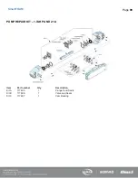
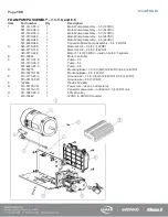
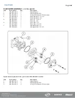
FOAM PUMP ASSEMBLY – 3.3, 5.0, and 6.5
Item
Part number
Qty
Description
1.
501-3120-05-0
1
Motor/Pump Assembly – 3.3 (12VDC)
501-3120-06-0
1
Motor/Pump Assembly – 3.3 (24VDC)
501-3130-05-0
1
Motor/Pump Assembly – 5.0 (12VDC)
501-3130-06-0
1
Motor/Pump Assembly – 5.0 (24VDC)
501-4480-04-0
1
Motor/Pump Assembly – 6.5 (24VDC)
501-4480-06-0
1
Converter/Motor/Pump Assembly – 6.5 (12VDC)
A.
045-0770-00-0
1
Motor 3/4 HP – 3.3/5.0 (12VDC)
045-0770-01-0
1
Motor 3/4 HP – 3.3/5.0 (24VDC)
045-0770-02-0
1
Motor 1-1/4 HP 24VDC – used on both 6.5 systems
B.
610-00044
1
Motor Controller
C.
501-3110-00-0
1
Pump – 3.3
501-3130-00-0
1
Pump – 5.0
501-4480-00-0
1
Pump – 6.5
D.
019-02276
1
Mounting Base – 3.3/5.0 (both 12/24VDC) & 6.5 (24VDC)
019-02276-100
1
Mounting Base – 6.5 (12VDC)
E.
513-0770-00-0
1
Ground wire – 3.3/5.0 (both 12/24VDC) & 6.5 (24VDC)
513-00174-020
1
Ground wire – 6.5 (12VDC)
F.
122609
1
Diode 45V 240A
G.
513-00125-001
1
Power wire – used on all systems
513-00174-010
1
Converter power wire – added on 6.5 (12VDC) only
H.
017-0680-00-0
1
FPG drive key
I.
610-00082
1
12VDC to 24VDC Converter
Summary of Contents for MiniCAFS 2.1A
Page 3: ...Page 2 SmartFOAM NOTES...
Page 16: ...Page 15 SmartFOAM SYSTEM DIAGRAM Figure 6 Typical Hale SmartFOAM 2 1A and 1 7AHP System...
Page 17: ...Page 16 SmartFOAM Figure 7 SmartFOAM 3 3 5 0 6 5 Single Tank System with In line Strainer...
Page 18: ...Page 17 SmartFOAM Figure 8 SmartFOAM 3 3 5 0 6 5 Single Tank withMSTandIn lineStrainer...
Page 19: ...Page 18 SmartFOAM Figure 9 SmartFOAM 3 3 5 0 6 5 Single Tank withMSTandFSSeriesStrainer...
Page 20: ...Page 19 SmartFOAM Figure 10 SmartFOAM 3 3 5 0 6 5 Dual Tank withMDTIIandIn lineStrainers...
Page 21: ...Page 20 SmartFOAM Figure 11 SmartFOAM 3 3 5 0 6 5 Dual Tank withMDTIIandFSSeriesStrainer...
Page 22: ...Page 21 SmartFOAM Figure 12 SmartFOAM 3 3 5 0 6 5 Dual Tank withADTandIn lineStrainers...
Page 23: ...Page 22 SmartFOAM Figure 13 SmartFOAM 3 3 5 0 6 5 Dual Tank withADTandFSSeries Strainers...
Page 48: ...Page 47 SmartFOAM Figure 28 Typical 4 Inch Check Valve Installation Midship Pump...
Page 59: ...Page 58 SmartFOAM Figure 43 ADT Option Air Hose Connections Part 2...
Page 68: ...Page 67 SmartFOAM Figure 55 Top Mount Low Level Sensor Assembly...
Page 77: ...Page 76 SmartFOAM NOTES...
Page 90: ...89 Page 89 SmartFOAM NOTES...