background image

USER OPERATION AND MAINTENANCE

HP SERIES

PORTABLE PUMPS

29

The HP Series portable pumps are

designed to provide years of reliable

service with a minimum of maintenance

on the pump end.  The pump must be

cleaned and flushed out after each use.

Failure to clean and flush the pump may

degrade pump performance.  The only

maintenance that is usually required on

a regular basis is to hydrostatically test

the pump each year.

LEAK TEST

A leak test of the pump must be

performed each year.  The leak test will

be conducted at the pump working

pressure.

WARNING:  TO PREVENT
ACCIDENTAL STARTING

 when

servicing the engine or pump
always disconnect the
negative wire from battery
terminal.

CHECK OIL LEVEL (HP100 GEARBOX)

The HP100 pump has a gearbox that

requires routine maintenance.  The oil

should be checked in the gearbox every

eight hours of operation and after each

use of the pump.  The following

procedures are used to check the oil

level in the HP100 gearbox.

1.  Place pump on a level work

surface to gain access to the

gearbox.

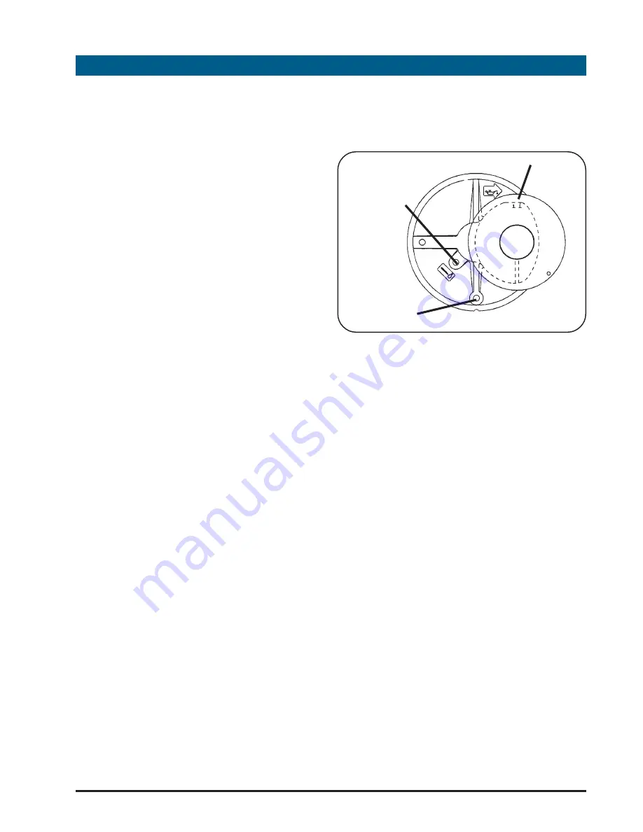
2.  Locate the oil fill fitting, the oil level

plug and the oil drain plug on the

pump gearbox.

3.  Loosen oil level plug with wrench

and begin to remove slowly.  If the oil

is at the proper level there should be

a slight trickle of oil from around the

plug.

4.  Replace plug and tighten.  If oil

needs refilling remove oil fill fitting,

vent and oil level plug.  Add new

gear oil (SAE  30) through oil fill fitting

until oil starts to flow from oil level

plug.  Replace and tighten oil level

plug.

8

PUMP MAINTENANCE

OIL DRAIN PLUG

OIL FILL FITTING

OIL LEVEL PLUG

Summary of Contents for HP 100

Page 1: ...and maintenance requirements set forth in this operating and maintenance manual may result in serious personal injury and or damage to equipment WARNING MANUAL P N 029 0020 24 0 REV E 2004 HALE PRODUC...

Page 2: ...HP SERIES PORTABLE PUMPS USER OPERATION AND MAINTENANCE 2...

Page 3: ...TDESCRIPTION 8 3 OPERATINGCONTROLDESCRIPTION 14 4 INITIALCHECKOUTPROCEDURES 18 5 STARTINGPROCEDURES 24 6 SHUTDOWN ANDSTORAGEPROCEDURES 26 7 MAINTENANCESCHEDULE 28 8 PUMP MAINTENANCE 29 9 ENGINE MAINTE...

Page 4: ...HP SERIES PORTABLE PUMPS USER OPERATION AND MAINTENANCE 4...

Page 5: ...m the spill and avoid creating any ignition until the gasoline has evaporated 8 DONOTSTORE SPILL ORUSE GASOLINE NEAR AN OPEN FLAME or devices such as a stove furnace or water heater which utilize a pi...

Page 6: ...gth of flexible piping is required to prevent damage to the pump and engine 12 Do not run pump for more than 45 seconds without suction established pressure of 7 BAR 100 PSIG Under normal operation co...

Page 7: ...ORDRY CARTRIDGE 14 For proper engine operation keep controls and linkages clean and free of debris 15 Periodically clean muffler area to remove all grass paper leaves dirt or other combustible debris...

Page 8: ...ation includes pump ends made of strong corrosion resistant aluminum alloy held together with a stainless steel clamp The pump engine is air cooled and the portable models are enclosed with high stren...

Page 9: ...in a smaller storage compartment The discharge valve on the portable pump version swivels through 175o for PORTABLE PUMP HANDLE POSITIONS EXTENDED TO END FOLDED FOR STORAGE EXTENDED TO SIDE Each pump...

Page 10: ...s meets or exceeds NFPA1921 requirements For complete NFPA1921 compliance the pumping units must be marked with specific labels Consult factory if these labels are required HALE PRODUCTS INC ease of d...

Page 11: ...EAD FLOW ELEVATION SEA LEVEL ENGINE BRIGGS STRATTON MODEL VANGUARD 18 OHV 18 HP 4000 RPM PERFORMANCE BASED ON 95 OF ENGINE MANUFACTURER S MAXIMUM BRAKE HORSEPOWER 0 50 100 150 200 250 GPM 0 20 40 60 8...

Page 12: ...EVEL ENGINE BRIGGS STRATTON MODEL VANGUARD 18 OHV 18 HP 4000 RPM PERFORMANCE BASED ON 95 OF ENGINE MANUFACTURER S MAXIMUM BRAKE HORSEPOWER 0 100 200 300 400 GPM 0 20 40 60 80 100 120 140 PSI 0 200 400...

Page 13: ...TEEL ENGINE SHAFT WITH BRONZE SLEEVE ENGINE SHAFT WITH BRONZE SLEEVE ENGINE SHAFT WITH BRONZE SLEEVE BEARING BALL N A N A N A PRIMING EXHAUST VENTURI EXHAUST VENTURI EXHAUST VENTURI EXHAUST VENTURI MA...

Page 14: ...WITCH The Master switch is located below the start button and is used to close the electrical circuits on the pump to enable operation This is a rocker type switch which when the side is depressed ene...

Page 15: ...lds up the light will go out to indicate there is sufficient oil pressure in the engine The engine is equipped with an oil pressure switch that activates the low oil pressure light when pressure drops...

Page 16: ...ischarge hose before disconnecting the hose 13 LIGHTAND CHARGING SOCKET An optional marine grade light and charging socket is located on the top cover of the HP series portable pumps This socket has a...

Page 17: ...BLE PUMPS 17 1 4 TURN BALL VALVE SHOWN IN NORMAL OPERATING POSITION EXHAUST PRIMER VALVE ASSEMBLY EXHAUST PRIMER ASSEMBLY operated with a positive pressure source the valve must be closed to prevent w...

Page 18: ...ION Always connect the black wire to the negative battery terminal last Connect the red cable to the positive terminal and connect the black cable to the negative terminal Make sure that the plastic o...

Page 19: ...and choke control to the engine Secure in place with the clamps provided After the connections are made ensure the controls work smoothly There may be excess cable after the connections are made Make...

Page 20: ...activating the battery on the portable pump or installing the X series pump prior to placing the pump into DISCHARGE GAUGE TUBING CONNECTION SUCTION GAUGE TUBING CONNECTION making discharge piping co...

Page 21: ...verflowing The tank is designed to provide sufficient expansion space when the tank is full When refilling the fuel tank ensure the pump is level to prevent overfilling or fuel being spilled on the gr...

Page 22: ...hose has no bends or loops that are higher than the suction connection of the pump that would trap air and prevent priming of the pump engine crankcase Before placing pump into operation for the firs...

Page 23: ...NNECT DISCHARGE HOSE After connecting discharge hose ensure the discharge valve is closed Remove all kinks and sharp bends from the discharge hose 7 CLOSE PUMP DRAINS Make sure the pump and discharge...

Page 24: ...lit This indicates the battery is good and the pump is ready to start If the oil light is not lit check the battery connections and ground connections It may be necessary to start the pump using the...

Page 25: ...tive pressure connected to the inlet ensure the 1 4 turn valve on the exhaust primer assembly is in the closed position prior to starting the pump 7 ESTABLISH DISCHARGE Once suction is established as...

Page 26: ...e encountered 1 MAKE HOSE CONNECTIONS Connect suction hose and place end in a CLEAN WATER source Then connect discharge hose and prepare to operate pump 2 ENERGIZE PUMP Start engine and establish wate...

Page 27: ...NCE HP SERIES PORTABLE PUMPS 27 Also wipe the pump covers down with a clean damp cloth If necessary use a mild soap and water solution to clean plastic covers 10 STORE PUMP Return pump to storage comp...

Page 28: ...50 Hours or Monthly 100 Hours or Yearly Yearly ENGINE MAINTENANCE Check Oil Level Change Oil NOTE 1 Change Oil Filter Clean Foam Air Cleaner Pre Cleaner NOTE 2 Service Air Cleaner Cartridge NOTE 2 Cle...

Page 29: ...LLEVEL HP100GEARBOX The HP100 pump has a gearbox that requires routine maintenance The oil should be checked in the gearbox every eight hours of operation and after each use of the pump The following...

Page 30: ...Return pump to storage or operation CHANGE GEARBOX OIL HP100 The oil in the gearbox of the HP100 should be changed after every 50 hours of operation The following procedures shall be used to change th...

Page 31: ...emove hex head screws and separate the ejector body from the exhaust valve body 7 Remove check valve ball from ejector body 8 Using wire brush and tip cleaners carefully remove carbon from ejector noz...

Page 32: ...Unscrew oil dipstick cap remove oil dipstick and check oil level Proper oil level is when oil is visible on the dipstick end between the ADD and FULL marks 6 Screw dipstick firmly into place until ca...

Page 33: ...th the proper grade of oil NOTE The engine will require a minimum of 3 pints 1 4 liters if the oil filter is not replaced and 3 5 pints 1 6 liters if the oil filter is replaced 7 Check oil level and r...

Page 34: ...assembly in a work area where access can be made to the oil drain fitting Ensure the pump is level 2 On portable pump unlatch and remove covers to gain access to engine Disconnect the negative battery...

Page 35: ...ttery cable 2 Remove air cleaner cover assembly by releasing the latches on either side of the cover and lift cover off pump NOTE Before installing new filter lightly oil filter gasket with fresh clea...

Page 36: ...oam pre cleaner from cartridge 5 Service foam pre cleaner a Wash in liquid detergent and water b Squeeze dry in a clean cloth c Saturate in engine oil Squeeze in clean absorbent cloth to remove all ex...

Page 37: ...e clogged after prolonged service After every 100 hours of operation or yearly remove the pump covers and blower housing and clean the areas shown in the illustration to prevent engine damage caused b...

Page 38: ...4 Remove the three bolts that hold the exhaust primer assembly on the muffler Remove the exhaust primer assembly 5 Remove the spark arrestor screen assembly from the muffler 6 Clean the spark arresto...

Page 39: ...In some areas local law requires the use of a resistor spark plug to suppress ignition signals If the engine was originally equipped with a resistor spark plug be sure to use the same type of spark p...

Page 40: ...el filter in the fuel line 4 Place a container under the fuel filter to catch any excess fuel that may be in the lines 5 Remove the fuel filter from the fuel lines 6 Place new clips on the fuel lines...

Page 41: ...nnect battery load test instrument to the terminals and place battery under simulated starting load with the test instrument The meter should read 9 volts or more when the simulated starting load is a...

Page 42: ...y shall be to give Hale written notice thereof and to request a Returned Goods Authorization Upon receipt of the Returned Goods Authorization the buyer will return the non conforming material to Hale...

Page 43: ...DIMENSIONS X SERIES PUMP MOUNTING DRAWINGS The following pages contain drawings to assist in the mounting of X Series pumps on apparatus The drawings are not to scale but will assist the installer in...

Page 44: ...HP SERIES PORTABLE PUMPS USER OPERATION AND MAINTENANCE 44 X Series Pump Mounting Dimensions...

Page 45: ...USER OPERATION AND MAINTENANCE HP SERIES PORTABLE PUMPS 45 X Series Pump Base Mounting Hole Location Dimensions...

Page 46: ...HP SERIES PORTABLE PUMPS USER OPERATION AND MAINTENANCE 46 X Series Pump Control Panel Mounting Hole Location Dimensions...

Page 47: ...imensions I SERIES PUMP MOUNTING DRAWINGS The following pages contain drawings to assist in the installation of I Series pumps on apparatus The drawings are not to scale but will assist the installer...

Page 48: ...HP SERIES PORTABLE PUMPS USER OPERATION AND MAINTENANCE 48 I Series Pump Dimensions...

Page 49: ...USER OPERATION AND MAINTENANCE HP SERIES PORTABLE PUMPS 49 12 ELECTRICAL WIRING DIAGRAMS HP and HP X Series Electrical Wiring Diagram...

Page 50: ...HP SERIES PORTABLE PUMPS USER OPERATION AND MAINTENANCE 50 HP I Series Electrical Wiring Diagram...

Page 51: ...ries and I Series pumps Each part of the pump is identified on the illustration with an index number Located in the list on the page next to the illustration are the Hale Products Inc part numbers for...

Page 52: ...HP SERIES PORTABLE PUMPS USER OPERATION AND MAINTENANCE 52 6 3 1 5 4 PL 1 HP SERIES PUMP COMPONENT IDENTIFICATION...

Page 53: ...0 HP300X PORTABLE PUMP EA 545 4080 00 0 HP400 PORTABLE PUMP EA 545 4080 02 0 HP400X PORTABLE PUMP EA 1 HP SERIES PUMP END FOR DETAILS SEE PL 3 FOR HP200 HP300 AND HP400 PL 4 FOR HP100 1 0 EA 2 045 068...

Page 54: ...TION AND MAINTENANCE 54 18 30 15 14 36 11 17 27 28 29 24 32 23 21 20 22 31 27 28 29 12 13 10 16 10 11 3 2 5 7 1 19 33 11 6 6 6 4 8 9 25 26 PL 2 HP SERIES PORTABLE PUMP COVERS AND CARRYING HANDLES 35 3...

Page 55: ...7 0170 08 0 BATTERY HOLD DOWN 1 0 EA 15 200 0600 00 0 BATTERY 1 0 EA 16 047 0030 10 0 BATTERY BASE 1 0 EA 17 019 0740 01 0 BATTERY SUPPORT BRACKET 1 0 EA 18 547 0910 01 0 FRAME MEMBER REAR 1 0 EA 19 5...

Page 56: ...HP SERIES PORTABLE PUMPS USER OPERATION AND MAINTENANCE 56 11 10 12 13 14 15 12 16 17 18 7 8 5 4 1 3 5 6 9 2 1 19 20 19 21...

Page 57: ...0 AND HP400 X SERIES 1 0 EA 8 046 0050 00 0 46DW GASKET 1 0 EA 9 038 1270 01 0 1 4 DRAIN VALVE PLTD BRASS 1 0 EA 10 242 0880 00 0 V BAND CLAMP 10 125 IN DIAMETER 1 0 EA 11 001 0780 00 0 HP300 400 PUMP...

Page 58: ...HANDWHEEL HP SERIES DISCHARGE 1 0 EA 5 210 0805 11 0 NUT M8 1 25 STNLS STL LOCKING 9 0 EA 6 097 1750 03 0 HP100 VALVE WASHER 1 0 EA 7 097 1760 01 0 HP100 VALVE SEAL WASHER 1 0 EA 8 097 1750 02 0 HP100...

Page 59: ...0 01 0 HP100 IMPELLER WASHER 1 0 EA 27 016 0980 00 0 HP100 IMPELLER 1 0 EA 28 017 0260 01 0 HP100 IMPELLER KEY 1 0 EA 29 296 5050 06 0 HP100 MECHANICAL SEAL 1 0 EA 30 040 2540 00 0 254 NITRILE SEAL RI...

Page 60: ...HP SERIES PORTABLE PUMPS USER OPERATION AND MAINTENANCE 60 3 2 13 12 11 16 15 14 20 18 17 19 18 21 22 17 18 7 8 1 6 5 4 10 PL 5 HP400 DISCHARGE MANIFOLD 9...

Page 61: ...0 0 2308 210 O RING 1 0 EA 11 038 1220 01 0 1 8 DRAIN VALVE PLTD BRASS 2 0 EA 12 097 1840 01 0 2 5 INCH ISO BSP SEAL WASHER 4 0 EA 13 038 1510 00 0 HP300 DISCHARGE VALVE BODY 2 0 EA 14 040 2310 00 0 2...

Page 62: ...HP SERIES PORTABLE PUMPS USER OPERATION AND MAINTENANCE 62 3 2 1 9 8 7 6 5 4 13 10 11 12 14 15 PL 6 HP300 DISCHARGE VALVE ASSEMBLY...

Page 63: ...0 HP300 VALVE WASHER 1 0 EA 6 097 1760 00 0 HP300 VALVE SEAL WASHER 1 0 EA 7 097 1750 00 0 HP300 VALVE BACKUP WASHER 1 0 EA 8 041 0480 00 0 VALVE STEM 1 0 EA 9 041 0470 00 0 VALVE SHAFT 1 0 EA 10 040...

Page 64: ...HP SERIES PORTABLE PUMPS USER OPERATION AND MAINTENANCE 64 6 26 18 17 24 16 7 14 12 11 2 1 1 2 3 4 5 10 11 12 8 9 13 15 21 22 20 23 12 11 19 25 17 27 28 29 PL 7 HP SERIES PUMP EXHAUST PRIMER ASSEMBLY...

Page 65: ...I SERIES PUMP 1 0 EA 11 218 0812 02 0 SCREW M8 1 25 X 25 H H SST 7 0 EA 12 097 0560 02 0 WASHER 5 16 300 SER SST LOCK 6 0 EA 13 046 0850 01 0 EJECTOR GASKET 1 0 EA 14 082 0348 02 0 ELBOW 3 8 NPT X 1...

Page 66: ...HP SERIES PORTABLE PUMPS USER OPERATION AND MAINTENANCE 66 1 3 2 3 8 5 4 PL 8 HP SERIES PUMP ENGINE MOUNTING 9 SERIAL NUMBER NAMEPLATE 7 6 10 1 14 11 15 13 7 12...

Page 67: ...0200 01 0 ENGINE MOUNTING BASE 1 0 EA 9 045 0680 00 0 B S MODEL 350447 0080 ENG B35 1 0 EA HP I SERIES MOUNTING 10 547 0190 03 0 BASE HP I SERIES 1 0 EA 11 097 0560 02 0 WASHER LOCK SST 4 0 EA 12 097...

Page 68: ...5 0 0 400 DISCH PRESS GAGE LIQ FIL A 1 0 EA 8 200 0170 01 0 SWITCH ON OFF HP SERIES 1 0 EA 9 200 0120 03 0 STARTER SWITCH 1 0 EA 10 013 0340 04 0 THROTTLE EXHAUST VALVE CONTROL LEVER 2 0 EA 11 018 120...

Page 69: ...EL HOSE 1 9 FT 6 242 0620 01 0 HOSE TUBING CLAMP 6 0 EA 7 082 0240 02 0 CONNECTOR 1 4MNPT X 1 4ID HOSE 1 0 EA 8 340 0060 02 0 1 4 ID FUEL HOSE 1 9 FT 9 BAS 493629 FUEL FILTER ASSEMBLY 1 0 EA 10 003 00...

Page 70: ...3 218 0608 19 0 SCREW M6 1 X 16 SOC HD SST LOCK 3 0 EA 4 BAS 805449 WASHER 3 0 EA 5 BAS 805292 OIL FILTER HOLDER 1 0 EA 6 046 6600 00 0 GASKET HP SERIES OIL FILTER 2 0 EA 7 005 1150 00 0 OIL FILTER AD...

Page 71: ...0 NUT M8 1 25 STNLS STL LOCKING 12 0 EA 2 097 1850 00 0 WASHER 1 13 OD X 0 34 ID X 0 091 IN THK ZINC PLTD STL 4 0 EA 3 218 0850 12 0 SCREW M8 1 25 X 100 H H ZINC PL 4 0 EA 4 097 0520 00 0 1 FZZ 264A R...

Page 72: ......

Reviews: