Page 89
RoboScrub Service Manual
1
1
2
2
3
3
4
4
5
5
6
6
7
7
8
8
D
D
C
C
B
B
A
A
Title
Number
Revision
Size
A3
Date:
2017/5/24
Sheet of
File:
G:\AD PCB\..\Sht1.SchDoc
Drawn By:
MINUTEMAN SYSTEM DIAGRAM
A
1 / 2
1
11
10
20
P3
1
8
7
14
P2
1
2
P1
Ref_0V
SQUEE
MOTOR
BRUSH
DECK
MOTOR
TRACTION MOTOR
BRUSH MOTOR
VACUUM MOTOR
BAT:24V
T TRACTION-
BAT-
BAT+
BRUSH+
BRUSH-
VACUUM-
KCCA0237 SCRUBBER CONTROLLER
ACCELERATOR
PM
MOTOR
PM
MOTOR
PM
MOTOR
PM
MOTOR
PM
MOTOR
ACCEL_WIPER
FRESH WATER LEVEL SWITCH
NC
DIRTY WATER LEVEL SWITCH
NO
SEAT SWITCH
NO
DGND
BRAKE
COIL
CLEAN_DOSE_ADJUST_COIL
FRESH_WATER_FLOW_COIL
+24V
1
2
3
4
5
6
7
8
9
10
REVERSE
ALARM
DGND
KEYSW
3
4
2
1
E-STOP SWITCH
KCSD0061
2
3
4
6
7
9
10
11
12
13
17
18
19
ManLiang Wang
1
4
P4
2
1
F1
4
3
1
2
Main Contactor (150A)
1
2
3
4
J6
CAN_H
DGND
CAN_L
BRAIN AUTONOMY MODULE
KEY SW
NO
F2
2A
ACCEL_GND
ACCEL_POWER
1
2
3
1
2
3
2.5K
0K
1
2
3
4
1
1
2
2
1
1
2
2
CAN_H
CAN_L
OEM DASHBOARD MODULE1
DGND
4
3
1
2
DGND
BRUSH UNLOAD SWITCH
UNLOAD
LOAD
-
+
+
-
+
-
+
-
3
4
2
1
E-STOP SWITCH
(FRONT)
(REAR)
BEACON
Summary of Contents for Minuteman MAX RIDE 20
Page 1: ...Minuteman International Inc A Member of the Hako Group RoboScrub 20 Service Manual...
Page 3: ...Page 4 RoboScrub Service Manual Technical Specifications...
Page 4: ...Page 5 RoboScrub Service Manual...
Page 5: ...Page 6 RoboScrub Service Manual Limited Warranty...
Page 6: ...Page 7 RoboScrub Service Manual...
Page 8: ...Page 9 RoboScrub Service Manual Remove back panel...
Page 9: ...Page 10 RoboScrub Service Manual Secure panel for ease of access...
Page 10: ...Page 11 RoboScrub Service Manual Locate and disconnect P3 connector from controller...
Page 14: ...Page 15 RoboScrub Service Manual Testing Pedal Circuit Bypass Seat Switch Circuit...
Page 15: ...Page 16 RoboScrub Service Manual Bypass Seat Switch Circuit...
Page 16: ...Page 17 RoboScrub Service Manual Remove back access cover...
Page 23: ...Page 24 RoboScrub Service Manual REMOVE STEERING SPINDLE DRIVE MOTOR AND PLACE ON WORKBENCH...
Page 26: ...Page 27 RoboScrub Service Manual...
Page 40: ...Page 41 RoboScrub Service Manual If no continuity present repalce UP TRUNK...
Page 47: ...Page 48 RoboScrub Service Manual Steering Place steering wheel in zero position as shown below...
Page 50: ...Page 51 RoboScrub Service Manual Turn machine on when prompted enter Operator PIN 1337...
Page 51: ...Page 52 RoboScrub Service Manual Enter Settings...
Page 52: ...Page 53 RoboScrub Service Manual...
Page 54: ...Page 55 RoboScrub Service Manual Enter Service Tools...
Page 55: ...Page 56 RoboScrub Service Manual Enter Steering...
Page 56: ...Page 57 RoboScrub Service Manual Enter Steering Assembly...
Page 57: ...Page 58 RoboScrub Service Manual Enter Sensor View...
Page 61: ...Page 62 RoboScrub Service Manual Back out to Steering Assembly screen Enter steering longevity...
Page 62: ...Page 63 RoboScrub Service Manual Follow on screen instructions...
Page 64: ...Page 65 RoboScrub Service Manual Back out to steering assembly screen and select run...
Page 65: ...Page 66 RoboScrub Service Manual Follow on screen instructions...
Page 66: ...Page 67 RoboScrub Service Manual Continued...
Page 73: ...Page 74 RoboScrub Service Manual MinuteMan RoboScrub 20 Replacing the MinuteMan BCM...
Page 75: ...Page 76 RoboScrub Service Manual MinuteMan RoboScrub 20 Replacing the MinuteMan BCM...
Page 77: ...Page 78 RoboScrub Service Manual Lower Lidar Removal Lower Lidar Removal...
Page 78: ...Page 79 RoboScrub Service Manual Front Panel Removal...
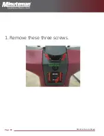
Page 79: ...Page 80 RoboScrub Service Manual 1 Remove these three screws...
Page 80: ...Page 81 RoboScrub Service Manual 2 Remove these two screws Remove Upper Lidar cover plate...
Page 82: ...Page 83 RoboScrub Service Manual...
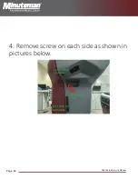
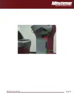
Page 83: ...Page 84 RoboScrub Service Manual 4 Remove screw on each side as shown in pictures below...
Page 84: ...Page 85 RoboScrub Service Manual...
Page 85: ...Page 86 RoboScrub Service Manual Removal of lower jaw and Lidar...
Page 86: ...Page 87 RoboScrub Service Manual 1 Disconnect cables...
Page 87: ...Page 88 RoboScrub Service Manual 2 Remove these four screws Then remove bracket...
Page 90: ...Page 91 RoboScrub Service Manual 3 Remove these two screws Now Lidar is ready to remove...
Page 94: ...Page 95 RoboScrub Service Manual...
Page 125: ...Page 126 RoboScrub Service Manual Set Switch in Auto Position 11 o clock...
Page 126: ...Page 127 RoboScrub Service Manual...
Page 127: ...Page 128 RoboScrub Service Manual Place Switch in Manual Position 2 o clock...
Page 128: ...Page 129 RoboScrub Service Manual...
Page 136: ...Page 137 RoboScrub Service Manual Figure A Figure B...
Page 137: ...Page 138 RoboScrub Service Manual Figure C Figure D...
Page 138: ...Page 139 RoboScrub Service Manual...
Page 148: ...Page 149 RoboScrub Service Manual Turn key to off position disconnect batteries...


