25
Operation
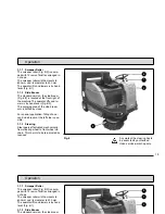
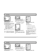
Sweeper roller lever
and lifted-up disposal (Fig. 10/1)
Two-Hand-Operation.
For lifting, lowering, swinging, to switch
on and off the sweeper roller and to re-
lease of lifted-up disposal.
- Sweeper roller lowering and switch
on = push lever
- Sweeper roller lifting and switch
off = pull in middle position
- Release of lifted-up disposal
function = pull lever
(see chapter „Emtying of the Dirt Hop-
per“).
Lifting and turn off the sweeper
roller, if the lever for the right
side broom is in lifting position.
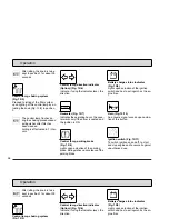
Side broom lever (Fig. 10/2)
To lift and lower the side broom or lower
and turn on the side broom and
sweeper roller in one process (Fig. 10/
1).
- Lower side broom = push lever.
- Lift side broom = pull lever.
Engine speed regulation knob
(Fig. 10/3)
To adjust the engine speed. Neutral
speed is attained by pulling the knob
up.
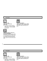
Suction fan / shaking system
(Fig. 10/4)
Knob position
(from bottom to top):
0
Activated vacuuming function
1
Deactivated vacuuming function
2
Shaking system ON
(pull knob to stop and then release)
If the yellow control lamp (Fig. 10/5) li-
ghts by ignition or with the engine run-
ning, actuate the shaking system
(position 2).
In this position, the shaking system is
operable and proceeds to jolting in 7 re-
peated intervals.
Summary of Contents for Jonas 1200 V
Page 1: ...Instruction Manual Hako Jonas 1200 V D 6300 10 6300 20...
Page 13: ...13 Safety information Fig 2 2 1 9 4 5 6 3 6 7 8 Safety information 5 6 3 8...
Page 22: ...22 Operation Operation...
Page 38: ...36 5 5...
Page 67: ......


