background image

Citytrac 4200

Citymaster 1200

Citycleaner

Service Documents

For internal use only

Status

March 2009

Page

31 of 108

5.1 Safety regulations

  The hydraulic system is under high pressure!

High-pressure fluids (fuel, hydraulic oil) escaping at high pressure can penetrate the skin and cause severe injuries. Therefore,
seek medical attention immediately to prevent the possibility of developing a severe infection!

  Use the applicable tools when searching for leaks to prevent the risk of injury!

  Before starting work on the hydraulic system, it must be depressurised and any devices attached must be lowered!

  When working on the hydraulic system, it is essential to switch the engine off and secure the vehicle against rolling away

(parking brake, wheel chock)!

  When connecting hydraulic cylinders and motors, pay strict attention to the method of connecting hydraulic hoses prescribed!

  If connections are swapped, there is a risk of reversed functioning (e.g. raise/lower) - risk of accident!

  Check hydraulic lines at regular intervals and replace them in the event of signs of damage or ageing!

The replacement hoses must fulfil the technical requirements stipulated by the equipment manufacturer!

Dispose of oils, fuel and filters according to the applicable laws!

Summary of Contents for Citytrac 4200

Page 1: ...aten Adjustments Baukomponenten Zulieferer Components Suppliers Hako Werke GmbH Technischer Kundendienst 23843 Bad Oldesloe Stand 03 2009 Vertraulich nur f r den internen Gebrauch For internal use onl...

Page 2: ...13 2 2 Overview service 15 3 0 Assembly and Mechanical Design 3 1 Articulated 4 wheel chassis 17 3 1 1 Articulated steering 17 3 1 2 Hydraulic motor 17 3 2 Accelerator 18 3 3 Engine hand throttle 20...

Page 3: ...tem diagram 40 5 3 2 Differential lock valve 43 5 3 3 Switching valve working transport mode 46 5 4 Work hydraulics 50 5 4 1 1 Valve manifold old 50 5 4 1 2 Valve manifold new 51 5 4 1 3 Torque valve...

Page 4: ...Front attachment device connector 84 6 7 Rear attachment device connector 87 6 8 Rear device connector assignment 89 6 9 Switching functions 91 6 10 Controller water regulation 94 6 11 Relay surface...

Page 5: ...Citytrac 4200 Citymaster 1200 Citycleaner Service Documents For internal use only Status March 2009 Page 5 of 108 Hako Citytrac 4200 Hako Citymaster 1200 Hako Citycleaner Product Description...

Page 6: ...g width 1 50 and 1 80 m with side ejection Snow clearance with spring mounted blade 1 50 and 1 70 m rear ejection or mulchmower Cutting height adjustment 3 10 cm in combination with hydraulic rollers...

Page 7: ...Status March 2009 Page 7 of 108 1 0 Product description Hako Citytrac 4200 Citymaster 1200 Citymaster Hand held suction hose Citycleaner Optionally equipped with the strong hand held suction Wet swee...

Page 8: ...suction fan water pump mower deck option 3 control console right 3 working lights 4 control console left 4 rotating beacon 5 control panel cabin roof 5 hazard flasher 6 pedals 6 pilot lamp direction...

Page 9: ...4 air flow openings 5 ignition lock 5 pilot lamp parking brake 6 reset switch for trip hourmeter 6 pilot lamp hydraulic fliud temperatur 7 socket 7 pilot lamp dirt hopper lifted 8 selector for plough...

Page 10: ...ente beim Citycleaner 1 Tastenfeld Heben und Senken 2 Drehzahlversteller Motor 3 Betriebstsundenz hler 4 Drehzahlversteller f r Schrubbaggregat 5 Z ndschlo 6 Resettaster f r Tagesstunden kilometerz hl...

Page 11: ...tatus March 2009 Page 11 of 108 1 2 3 4 5 1 opening for windscreen washer reservoir 1 coarse particle flap 2 parking brake 2 differential lock option 3 lever for recirculation water suction mouth 3 br...

Page 12: ...Citytrac 4200 Citymaster 1200 Citycleaner Service Documents For internal use only Status March 2009 Page 12 of 108 Hako Citytrac 4200 Hako Citymaster 1200 Hako Citycleaner Technical Data...

Page 13: ...p mm 1995 2200 Wheelbase mm 1430 Track gauge front mm 998 984 rear mm 998 984 Turning diameter outer mm 5125 5500 Weight Unloaden weight acc to StvZO kg 1400 1800 Gross vehicle weight kg 2500 Axle loa...

Page 14: ...sport mode automotive forwards kph 0 25 reverse kph 0 12 Work mode forwards kph 0 13 reverse kph 0 9 Tyres Size 26 x 12 00 12 8 PR 195 R 14 C Load bearing capacity kg 750 Air pressure bar 1 5 3 0 Whee...

Page 15: ...bolts for tight seating 130Nm 50h x Check ball heads of steering cylinder 50h x Check fresh air intake filter for cabin fan x x x x Check brake fluid level x x x x Check wearing plate in dirt hopper x...

Page 16: ...itytrac 4200 Citymaster 1200 Citycleaner Service Documents For internal use only Status March 2009 Page 16 of 108 Hako Citytrac 4200 Hako Citymaster 1200 Hako Citycleaner Assembly and Mechanical Desig...

Page 17: ...17 of 108 3 1 Articulated 4 wheel chassis 3 1 1 Articulated steering Pendulum articulated joint with shock absorption Maintenance Grease weekly Check condition of rubber stops and for signs of wear 3...

Page 18: ...rom throttle to accelerator pedal Adjust so that the microswitch on the accelerator pedal is actuated when the throttle is at the first notch The entire path of travel for the throttle must be free to...

Page 19: ...le to Transport mode actuate the parking brake and secure the machine by positioning chocks against the rear wheels Disconnect both cables from the accelerator pedal and check that the pedals are para...

Page 20: ...mode work hydraulics disabled Behind first notch Engine idling work mode 4 wheel max 12 5 km h Automotive mode work hydraulics enabled In front of the second notch Preferred speed 2450 rpm work mode 4...

Page 21: ...Citytrac 4200 Citymaster 1200 Citycleaner Service Documents For internal use only Status March 2009 Page 21 of 108 Hako Citytrac 4200 Hako Citymaster 1200 Hako Citycleaner Engine...

Page 22: ...del Series Cylinder Bore Speed Range Hako Plant 4 2 Technical data Cylinder bore stroke mm 88 x 90 Cubic capacity cm 3 2 190 Ignition sequence 1 3 4 2 1st cylinder on flywheel Direction of rotation An...

Page 23: ...er Service Documents For internal use only Status March 2009 Page 23 of 108 4 3 Overview of components Shutdown solenoid Fuel filter Dip stick Oil Pressure switch Oil filter Oil filling neck Thermosta...

Page 24: ...Citytrac 4200 Citymaster 1200 Citycleaner Service Documents For internal use only Status March 2009 Page 24 of 108...

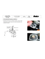
Page 25: ...tatus March 2009 Page 25 of 108 4 4 Crankshaft housing ventilation Complete the following every 1000 operating hours or every 2 years Check whether any oil or condensate has penetrated between the mem...

Page 26: ...he valve clearance must be checked every 1000 operating hours or at least once a year and readjusted as necessary During this maintenance work check whether the valve caps are set square on the valves...

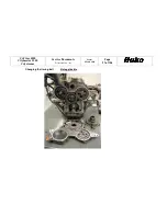
Page 27: ...Citytrac 4200 Citymaster 1200 Citycleaner Service Documents For internal use only Status March 2009 Page 27 of 108 Changing the timing belt Not applicable...

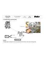
Page 28: ...nly Status March 2009 Page 28 of 108 4 6 Changing the injection pump Comment The pump flange and driving wheel are set up for the engine at the factory Do not loosen the flange bolts Pump driving whee...

Page 29: ...f a voltage drop a spring pulls the control shaft to engine shutdown If the shutdown mechanism fails the engine can be operated to a restricted level after disassembling the solenoid with the loss of...

Page 30: ...Citytrac 4200 Citymaster 1200 Citycleaner Service Documents For internal use only Status March 2009 Page 30 of 108 Hako Citytrac 4200 Hako Citymaster 1200 Hako Citycleaner Hydraulic Installations...

Page 31: ...ic system it must be depressurised and any devices attached must be lowered When working on the hydraulic system it is essential to switch the engine off and secure the vehicle against rolling away pa...

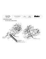
Page 32: ...only Status March 2009 Page 32 of 108 5 2 Hydraulic pumps 5 2 1 Overview of pump location Hydraulic pump Gear pump 1 circuit 1 mower suction fan Measuring points Drive high pressure forwards Feed pre...

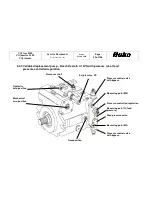
Page 33: ...xroth A 10VG with pressure cut off and pressure controlled regulation Pressure control valve with bypass Measuring point MB Pressure controlled regulation Measuring point G feed pressure Feed pressure...

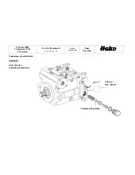
Page 34: ...00 Citymaster 1200 Citycleaner Service Documents For internal use only Status March 2009 Page 34 of 108 Feed pressure adjustment Comment Only check at operating temperature Compensating disks 22 bar a...

Page 35: ...2 3 Technical data and set values 3 2 1 4 Feed volumes Revolutions cm 3 46 Max speed Higher idling rpm 2750 25 1 Feed pressure at on load speed bar 22 2 3 High pressure A B bar 322 4 Pressure cut off...

Page 36: ...ntrol units Depending on the DA regulating valve pos 5 actuating the accelerator pedal causes the feed pressure to be supplied to the set piston which moves the hydraulic pump s pivoting disk in the r...

Page 37: ...the high pressure lines from the traction drive is to supply oil at 11 l min from the depressurised high pressure line to the tank This is necessary to replace the warmed oil in the closed circuit wit...

Page 38: ...connection G on the hydraulic pump When rear wheel drive is switched off the all wheel drive valve establishes a connection to the flow and return flow of the wheel motors to compensate for loss of oi...

Page 39: ...n Hydraulic oil supply for pump circuit 1 attachment devices e g mower mode suction fan mode 5 2 7 Gear pump ZP 2 Constant gear pump Sauer Sundstrand SNP 2 17 36 l min Hydraulic oil supply for pump ci...

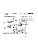
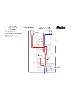
Page 40: ...2009 Page 40 of 108 5 3 Traction drive Hydraulicpump 5 3 1 System diagram Four wheel drive on Y13 not activated not energised Differential lock off Y11 not activated not energised Four wheel switching...

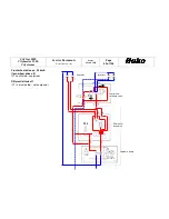
Page 41: ...internal use only Status March 2009 Page 41 of 108 Four wheel drive on Y13 not activated not energised Differential lock on Y11 activated energised Four wheel switching valve Differential lock valve H...

Page 42: ...nly Status March 2009 Page 42 of 108 Front wheel drive on 25 km h four wheel drive off Y13 activated energised Differential lock off Y11 not activated not energised Four wheel switching valve Differen...

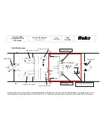
Page 43: ...low of the feed pressure to the tank and the distributing valve is actuated hydraulically The differential locking valve is basically comprised of two double action current dividers dividing and accum...

Page 44: ...0 Citymaster 1200 Citycleaner Service Documents For internal use only Status March 2009 Page 44 of 108 Y 11 approx 5 7 Compensating nozzle D2 Compensating nozzle D2 A B C X T P D2 D1 at opposit side o...

Page 45: ...Possible causes Diff locking valve does not switch on No power at the solenoid coil approx 5 7 Feed pressure too low or not provided Aperture in connection X is blocked Series piston jams O ring on se...

Page 46: ...e slower work mode results from distribution of the feed quantity to 4 wheel motors When activated Y13 energised the solenoid valve switches the feed pressure to the distributing valve and activates i...

Page 47: ...Status March 2009 Page 47 of 108 X A P2 P1 B T C A Feed Return flow from differential lock B Return flow Feed from the hydraulic pump P1 Feed Return flow from the hydraulic motor P2 Return flow Feed f...

Page 48: ...ial lock front 25 per wheel D1 Sperre zwischen Vorder und Hinterachse 50 per Achse D1 Diffential lock between front and rear axle 50 per axle View from machine side D1 D2 Bei Traktionsproblemen D se D...

Page 49: ...s March 2009 Page 48 of 108 Switching valve four wheel front wheel drive Possible faults Possible causes Valve does not switch No power at solenoid magnet coil approx 6 Feed pressure too low or not pr...

Page 50: ...ntinue d Contacts on the Y13 connector are in order no corrosion contacts fit correctly in the connector B on Pin 1 B on Pin 2 of X41 Check the resistance of coils on Y13 set value approx 6 e Switch t...

Page 51: ...es approx 6 Y2 Lower front attachment support approx 6 Y12 Front attachment support float lower approx 6 Y5 Proportional valve side brushes spreader approx 6 Y6 Work hydraulics on circulation off appr...

Page 52: ...direction M1 Messpunkt Sauggebl se M hwerk M1 measuring point work suction fan mower deck Y9 Beh lter heben 6 Y9 raise hopper 6 Y8 Besen ausschwenken 6 Y8 Brooms out 6 Y3 Frontaushebung heben 6 Y3 Ra...

Page 53: ...ve 195 bar suction fan mower Y4 CM 1200 Sauggebl se Y4 CT 4200 M hwerk Y4 CM 1200 suction fan Y4 CT 4200 mower 5 4 1 2 Steuerblock neu ab 30 09 2006 Valve mainfold new from 30 09 2006 Y9 Y10 Y8 Y3 Y7...

Page 54: ...0 bar mower stop DBV 195 bar Sauggebl se M hwerk Pressure relief valve 195 bar suction fan mower 5 4 1 2 Steuerblock neu ab 30 09 2006 Valve mainfold new from 30 09 2006 Y12 Frontaushebung senken Schw...

Page 55: ...ve manifold new from 30 09 2006 Stromregelventil auf Pos M2 neu hinzugekommen Mengenteiler auf A2 hat sich hierhin verschoben Siehe auch Umr stsatz 97056907 aus KUD 22 vom 30 08 2006 Current regulatin...

Page 56: ...Documents For internal use only Status March 2009 Page 52 of 108 5 4 1 3 Starting moment valve manifold components 4x each Ma 5 5 Nm 4 2 4 1 6 27 Ma 25Nm 9 27 Ma 25Nm 2 24 Ma 30Nm 3 24 Ma 40Nm 10 24 M...

Page 57: ...raulic valve vacuum fan suction turbine on mower on 12V 2000mA 6 Y5 Proportionalventil Seitenbesen Streuer Proportional valve side brooms spreader 4 6 5V 780 1060mA 6 Y6 Hydraulikventil Umlauf aus Arb...

Page 58: ...25 km h 12V 2000mA 6 Y16 Hydraulikventil Ger tetr ger dr cken Option Citycleaner Hydraulic valve front carrier pressure Option Citycleaner 0 95 2 5V 150 450mA 6 3 Y17 Hydraulikventil Ger tetr ger Sch...

Page 59: ...itycleaner Service Documents For internal use only Status March 2009 Page 55 of 108 5 4 2 1 Valve manifold system diagram before 30 09 2006 STEERING SIDE BRUSHES MOTOR FRONT ATTACHMENT SUPPORT PIVOTIN...

Page 60: ...e Documents For internal use only Status March 2009 Page 56 of 108 5 4 2 2 Valve manifold system diagram from 30 09 2006 Additional current regulating valve STEERING SIDE BRUSHES MOTOR FRONT ATTACHMEN...

Page 61: ...o the prescribed pressure 195 bar If the drive is switched off Y4 is no longer energised the control slide moves from valve Y4 back to its initial position and the connection of the control line from...

Page 62: ...6 In addition Y6 also closes the pressure regulator via the control line and shuttle valve Pos 8 The mechanical spring then restricts the flow of oil and a maximum of 195 bar is possible before the pr...

Page 63: ...ng plug must be connected for enabling side brushes spreading mode When the above speed is set the potentiometer is fully open and pivot attachment device is actuated the feed quantity from this line...

Page 64: ...0 of 108 5 4 4 Proportional throttle cartridge Attention When disassembling the throttle cartridge pay attention that the threaded flange is only turned clockwise to align the coils There must be a ga...

Page 65: ...fan off Y4 not connected Y T oil leakage line to tank Circulation approx 8 bar Y 4 Mower Suction fan Through the valve Y4 is the tankline of the hydraulic servo controlled pressure relief valve 195ba...

Page 66: ...ter 1200 Citycleaner Service Documents For internal use only Status March 2009 Page 62 of 108 CT 4200 mower on CM 1200 suction fan on Y4 connected Y 4 T oil leakage line to tank Mower Suction fan Circ...

Page 67: ...arch 2009 Page 63 of 108 CT 4200 spreader off CM 1200 side brushes off Y5 not connected Y5 M2 circulating pressure approx 22 bar cause DBV 6 is not switched STEERING SIDE BRUSHES MOTOR FRONT ATTACHMEN...

Page 68: ...64 of 108 CT 4200 spreader on CM 1200 side brushes on Y5 connected 195 bar SIDE BRUSHES MOTOR STEERING FRONT ATTACHMENT SUPPORT PIVOTING FAN MOTOR To feed circuit To feed circuit Pressure control val...

Page 69: ...n off Work hydraulics on Y6 and at least one consumer connected 195 bar STEERING SIDE BRUSH MOTOR FRONT ATTACHMENT MOTOR PIVOTING CONTAINER EMPTYING FAN MOTOR To feed circuit Pressure control valve op...

Page 70: ...ompound circuits mulchmower for the hydraulic quantity The current regulation ensures the current flowing through the magnet remains constant even when the power supply fluctuates or the magnet heats...

Page 71: ...ent in series 4 Switch on the machine ignition move the throttle to its work mode position 5 Switch the potentiometer on via the latching point and set to Minimum 6 Set the minimum current min P2 to 7...

Page 72: ...e g snowblade brushes 2 Pivots front attachment devices forwards back e g snowblade brushes 3 Coding plug for attachment detection lighting 4 Proportional regulation maximum 20 litres forward e g comp...

Page 73: ...8 5 4 8 Rear connections 1 Proportional regulation max 20ltr forward e g spreader suction gras leaf collector 2 Proportional regulation return 3 Plug X60 4 Proportional regulation max 20ltr forward e...

Page 74: ...Citycleaner Service Documents For internal use only Status March 2009 Page 70 of 108 5 5 Citycleaner Hydraulic View Rear frame from middle to right side hydraulic tank View Rear frame in driving direc...

Page 75: ...Citytrac 4200 Citymaster 1200 Citycleaner Service Documents For internal use only Status March 2009 Page 71 of 108 Y 18 Y17 Y 16 Valve block scrubdeck surface pressure regulation...

Page 76: ...Citytrac 4200 Citymaster 1200 Citycleaner Service Documents For internal use only Status March 2009 Page 72 of 108...

Page 77: ...Citytrac 4200 Citymaster 1200 Citycleaner Service Documents For internal use only Status March 2009 Page 73 of 108...

Page 78: ...Citytrac 4200 Citymaster 1200 Citycleaner Service Documents For internal use only Status March 2009 Page 74 of 108...

Page 79: ...Citytrac 4200 Citymaster 1200 Citycleaner Service Documents For internal use only Status March 2009 Page 75 of 108 Hako Citytrac 4200 Hako Citymaster 1200 Hako Citycleaner Electrical Installations...

Page 80: ...n Attention When working on the engine and the electrical installations always disconnect the battery minus pole Notes on the three phase generator Only allow the engine to run with the battery connec...

Page 81: ...s F fuses G batteries generators H control lamps K relays M starter electric motors stroke elements pumps R resistors potentiometers glow plugs S switches buttons V diodes X connectors potential distr...

Page 82: ...system can be seen on the circuit diagram Wiring diagram In addition to the information on the circuit diagram the wiring diagram illustrates all the components such as connectors plugs cables cable...

Page 83: ...act F8 Fan condenser air conditioning unit F9 12 V socket radio terminal 30 F10 Heater fan controller Air conditioning unit F11 Y6 Circulation off F12 Operating hour counter radio terminal 15 F13 Hydr...

Page 84: ...Windscreen wiper interval option K 9 Enable mower seat contact B8 mower switch S5 K10 Suction fan mower relay on K11 Indicator relay Identification Name Order No F1 F2 F3 F19 F21 F22 Fuse link C7 5 A...

Page 85: ...Cooling water level control unit 01081390 K15 Cooling water level relay 00744770 K16 Timer fuel valve 01141150 K17 Relay fuel valve 01041700 K19 Relay enable starter 00744770 K20 Relay dynamo option...

Page 86: ...Citytrac 4200 Citymaster 1200 Citycleaner Service Documents For internal use only Status March 2009 Page 82 of 108 6 5 Overview of electrical components Overview machine...

Page 87: ...itymaster 1200 Citycleaner Service Documents For internal use only Status March 2009 Page 83 of 108 Frontview cab Look at circuit board A2 Connectors control unit A1 View steering column View roof con...

Page 88: ...hydraulic functions Pins 1 5 are provided for this Pin 6 is for the lighting and Pin 7 is the PE connection Connector Order no 114 372 Service plug Order no 114 438 Jumper K10 Device support Seat con...

Page 89: ...off and on again Jumper pin 1 to pin 2 Optional operation as Citymaster or Citytrac not for mower operation The hydraulic circuit is only activated after switching on the mower circuit When the front...

Page 90: ...pin 2 pin 2 to pin 3 and pin 4 to pin 7 Operation as CM1200 The hydraulic circuit is only activated after switching on the mower circuit When the front attachment support is raised the attachment devi...

Page 91: ...nnector fulfils several functions It serves the lighting coding and power supply Pin assignment 1 Drive direction indicator left L 9 Not connected 2 Open at X13 1 10 Power supply for F23 3 Earth 31 11...

Page 92: ...108 Jumper pin 3 to pin 12 Operation as Citymaster or Citytrac with path depending spreader This enables the continual operation of the proportional hydraulic circuit depending of the way speed The co...

Page 93: ...of 108 6 8 Rear attachment device connector X64 7 pin This connector fulfils several functions It serves the lighting coding and power supply Pin assignment 1 Speedometer 2 Power supply for F23 3 Ope...

Page 94: ...s Citymaster or Citytrac with grass and leaf vacuum This enables the continual operation of the proportional hydraulic circuit The connector necessary to implement this bridging function belongs to th...

Page 95: ...B via K6 30 to K6 87 and further to F22 7 5A to switch S5 mower fan on and to K7 30 At the same time B is connected to K7 86 via the open switch S5 converter Relay K7 is switched and B is connected v...

Page 96: ...be 5 9 Ohm If resistance is ok check whether Y4 is mechanically jammed Solution Clean replace if necessary No Complete following tests Test fuses F5 F19 F7 F15 F6 F22 Test switches S1 B8 seat contact...

Page 97: ...vom X42 to K2 4 Check the inputs at K2 are ok check K2 replace if necessary Check fuse F19 replace as necessary Check the input from S20 to K2 7 The zero position switch drive pump S20 must be switche...

Page 98: ...Citytrac 4200 Citymaster 1200 Citycleaner Service Documents For internal use only Status March 2009 Page 94 of 108 6 10 Controller water regulation A5 Option Citycleaner 6150 00...

Page 99: ...ster 1200 Citycleaner Service Documents For internal use only Status March 2009 Page 95 of 108 6 11 Relais surface pressure A4 Option Digital input Power supply Analog input Output prop valve 1 Ground...

Page 100: ...Citytrac 4200 Citymaster 1200 Citycleaner Service Documents For internal use only Status March 2009 Page 96 of 108 Hako Citytrac 4200 Hako Citymaster 1200 Hako Citycleaner Options...

Page 101: ...acket is comprised of A foot pedal for the differential lock standard CT4200 Path dependent spreading option for CT4200 Rear attachment connections standard CT4200 Differential lock standard CT4200 Lo...

Page 102: ...itycleaner Service Documents For internal use only Status March 2009 Page 98 of 108 7 1 1 1 Electrical plan A3 Control unit B11 Speedometer compl K20 Generator relay R13 Potentiometer with switch R14...

Page 103: ...Citytrac 4200 Citymaster 1200 Citycleaner Service Documents For internal use only Status March 2009 Page 99 of 108...

Page 104: ...s March 2009 Page 100 of 108 7 1 1 2 Control unit A3 Option path depence spreader control Terminal strip Trimming potentiometer PIN P1 to P5 P5 Adjust max control current P4 Adjust min control current...

Page 105: ...PIN3 on PIN12 7 Measure the voltage between A3 PIN4 and A3 PIN8 again The value should be identical to the previous one 8 If the values are not identical readjust using the trimming potentiometer P1...

Page 106: ...200 Citymaster 1200 Citycleaner Service Documents For internal use only Status March 2009 Page 102 of 108 7 1 2 Rear connections Hydraulic plan SPREADER PLATFORM CONTAINER RAISE LOWER VALVE MANIFOLD B...

Page 107: ...vice Documents For internal use only Status March 2009 Page 103 of 108 7 2 Grass and leaf vacuum 8380 Hydraulic plan Hydraulic diagram Container lifting cylinder Suction fan Connection to Rear connect...

Page 108: ...1200 or CT4200 is not equipped with the multipurpose packet and thus equipped with the rear attachment device connector X64 the coding connector can also be connected on the front attachment device co...

Page 109: ...t GND 2 Operating voltage 15 3 Switch output against GND 4 Earth 31 5 Speed sensor PNP according to 12 V 6 Configuration on 12 V 7 Work hours Mileage on 12V 8 Operating voltage 30 Total operating hour...

Page 110: ...plied to Pin 7 in addition to Pin 8 and Pin 2 The work mileage counter also counts the pulses divided by the dividing factor at Pin 5 Select the button depicting a clock see above to set the time Then...

Page 111: ...r graph indicator alternating on red LED flashing switching output PIN 3 against GND Greater than or equal to 1 V Segment 1 and 2 on in alternation Greater than or equal to 1 5 V Segment 1 to 3 on Gre...

Page 112: ...Citytrac 4200 Citymaster 1200 Citycleaner Service Documents For internal use only Status March 2009 Page 108 of 108 7 4 High pressure cleaner 1139...

Reviews: