
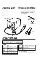


HEAT CONTROL
POWER
AIR CONTROL
1
2
3
4
8
7
6
5
1
2
3
4
8
7
6
5
Temperature control knob
Air flow control knob
OPERATION
●
●
●
●
●
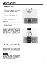
QFP Desoldering
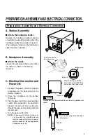
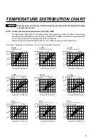
1. Adjust the air flow and temperature
control knobs.
Refer to the temperature distribution chart
(page 8) to adjust the air flow and temper-
ature control knobs. Wait for the temper-
ature to stabilize for a short period of time.
WARNING
If the thermal protector is tripped (the heater
lamp turns off during use), reduce the tem-
perature setting or increase the air flow. Be sure
not to operate the unit with temperature and air
flow settings that makes the thermal protector
trip. This could damage the unit.
2. Place the FP pick-up under the IC lead.
Slip the FP pick-up wire under the IC lead.
(Refer to the photo shown.)
If the width of the IC does not match the
size of the FP pick-up, adjust the width of
the pick-up by squeezing the wire. In case
of PLCC or small components such as
chip resistors, desolder by using
tweezers, etc.
3. Heating
Hold the handpiece so that the nozzle is
located directly over, but not touching the
IC, and allow the hot air to melt the solder.
Be careful not to touch the leads of the IC
with the nozzle.
4. Remove the IC.
Once the solder has melted, remove the
IC by lifting the FP pick-up.
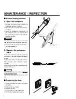
5. Remove any remaining solder.
After removing the IC, remove remaining
solder with a soldering iron and wick or
desoldering tool.
5
Summary of Contents for 850B
Page 15: ......


