background image

1

PACKING LIST

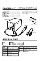
Check the contents of the Hakko 850B package and
confirm that all the items listed below are included:

Hakko 850B station ............................................. 1

Power cord .......................................................... 1

Handpiece holder ................................................ 1

FP pick-up ........................................................... 1

FP pick-up wire .................................................... 1

Instruction manual ............................................... 1

* This product does not include a nozzle. A large

selection of nozzles is available for the Hakko
850B. Select the nozzle or nozzles suitable for the
work to be performed.

SPECIFICATIONS

Name

Power consumption

Hakko 850B

100V – 280W  110V – 270W  120V – 300W
220V – 300W  230V – 310W  240V – 310W 

Power
Consumption

Pump

Capacity

Control 
temperature 

External 
dimensions

Weight

30 W
(Stand-by power consumption
 100 – 120V 2W, 220 – 240V 4W)

Diaphragm pump

23  /min (max)

100˚– 420˚C (212˚– 788˚F)
(Use A1126B)

225(l) × 160(w) × 145(h) mm.
8.9(l) × 6.3(w) × 5.7(h) in.

4 kg. (8.82 lb.)

 Station

Power
consumption

Total length
(w/o cord) 

Weight
(w/o cord)

100V – 250W  110V – 240W  120V – 270W
220V – 270W  230V – 280W  240V – 280W


196(l) mm / 7.72(l) in.

120 g / 0.26 lb.

 Handpiece

* This product is ESD-protected.
* Specifications and design subject to change without notice.

Hakko 850B station

Handpiece holder

Handpiece

FP pick-up
with (S) wire

FP pick-up wire (L)

Power cord

Summary of Contents for 850B

Page 1: ...fore operating the Hakko 850B Keep this manual readily accessible for reference TABLE OF CONTENTS PACKING LIST SPECIFICATIONS 1 SAFETY INSTRUCTIONS 2 PART NAMES 3 PREPARATION ASSEMBLY AND ELECTRICAL C...

Page 2: ...10V 270W 120V 300W 220V 300W 230V 310W 240V 310W Power Consumption Pump Capacity Control temperature External dimensions Weight 30 W Stand by power consumption 100 120V 2W 220 240V 4W Diaphragm pump 2...

Page 3: ...personnel or touch the metal parts near the nozzle Do not use the product near combustible gases or flammable materials Advise those in the work area that the unit can reach very high temperatures and...

Page 4: ...ntrol knob Handpiece holder mounting screw Handpiece holder mounting screw Fuse Handpiece holder Power receptacle Nozzle not included FP pick up with S wire Width of wire 14mm 0 55in FP pick up wire L...

Page 5: ...l of the station Figure 4 2 Place the handpiece on the holder Figure 5 3 Plug the power cord into a grounded wall socket After connection the automatic blowing function will start sending air through...

Page 6: ...he thermal protector trip This could damage the unit 2 Place the FP pick up under the IC lead Slip the FP pick up wire under the IC lead Refer to the photo shown If the width of the IC does not match...

Page 7: ...s with any soldering process however there is always the possibility of forming solder balls bridges between leads and inadequate solder joints Always inspect the finished solder joints for structural...

Page 8: ...e the heating element B Measure the resistance value Connect an ohmmeter across the connector terminals a The correct values are approxi mately 26 40 100 120V 70 100 220 240V If the resistance value i...

Page 9: ...4 2 7 3 6 Temperature Control Knob 1 5 8 4 2 7 3 6 Temperature Control Knob 1 5 8 4 2 7 3 6 Temperature Control Knob 1 5 8 4 2 7 3 6 Temperature Control Knob 1 5 8 4 2 7 3 6 500 932 F 300 572 F 100 2...

Page 10: ...e C 500 932 F 300 572 F 100 212 F Air Temperature C 500 932 F 300 572 F 100 212 F Air Temperature C 500 932 F 300 572 F 100 212 F Air Temperature C 500 932 F 300 572 F 100 212 F Temperature Control Kn...

Page 11: ...ture C 500 932 F 300 572 F 100 212 F Air Temperature C 500 932 F 300 572 F 100 212 F Temperature Control Knob 1 5 8 4 2 7 3 6 Temperature Control Knob 1 5 8 4 2 7 3 6 Temperature Control Knob 1 5 8 4...

Page 12: ...84 Pins 19 0 75 19 0 75 24 0 94 24 0 94 29 1 14 29 1 14 6 9 0 27 6 9 0 27 A 21 0 83 B 21 0 83 A 26 1 02 B 26 1 02 A 31 1 22 B 31 1 22 A 9 0 35 B 14 0 55 A1140B PLCC 11 5 11 5 0 45 0 45 28 Pins A1141B...

Page 13: ...e description Screws must be ordered separately Item No 1 2 3 4 5 6 7 8 Part No B2544 A1143 A1144 A1145 A1146 B1188 B1441 B2556 B1354 B2634 B2635 Part Name Handle Heating element Heating element Heati...

Page 14: ...2424 B2425 B2426 B2436 Part Name Cover Handpiece holder Sound proof tank Air pump Air pump Air pump Silicone tube Fuse Fuse Power receptacle Chassis Radiation sheet P W B P W B P W B P W B Switch Air...

Page 15: ......

Reviews: