background image

6

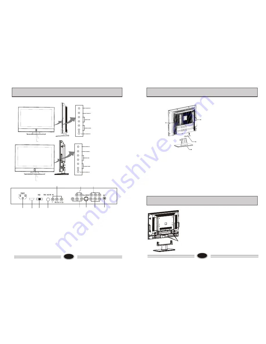
WALL MOUNT SWITCHING SUPPORT ASSEMBLY INSTRUCTIONS

(1) In order not to scratch the 
      TV set, it is recommended 
       putting the TV set with face 
       down on the soft and clean 
       blanket.
(2)Disassemble the six screws 
     from base and remove the 
     base. (This item will be
     cancelled if the product is 
     without base.)
(3)Mount the airproof board.
(4)Take out the switching 
      support from the accessory 
      bag,  and use four M5

×

16 

      screws (included in the 
      

Base 

Switching support

Switching support

Airproof board

BUTTONS AND INTERFACE  POSITION

5

Front control panel

Back interface

1. Power input socket
2. Antenna input 
3. AV2 input 
4. AV1 input 
5. S-VIDEO input
6. YPbPr or S-VIDEO audio input
7. AV output
8. YPbPr input
9. VGA audio input interface
10. VGA input
11. HDMI input

1

2

4

5

7

9

10

8

6

3

HDMI

11

(Y/Pb/Pr)- L-IN  R-IN

V-OUT   L-OUT R-OUT

AV2   L    R

AV1    L    R

Power button

Program down/up button

Volume down/up button

TV/AV switch button

Menu button

CH-

TV/AV

MENU

CH+

VOL-

VOL+

Power indicator

Remote sensor

Power indicator

Remote sensor

Power button

Program down/up button

Volume down/up button

TV/AV switch button

Menu button

CH-

TV/AV

MENU

CH+

VOL-

VOL+

L26A10A

/

L32A10A

/

L37A10A

L40A10A

      accessory bag) to fix the switching support on the back of complete set.
(5)The remaining four M5

×

16 screws in the accessory bag are used to mount the wall 

     mount parts.(The wall mount parts are in the wall mount box.)
(6)After completing the above operations, the complete set can be mounted on the wall 
     mount bracket.(Wall mount bracket operations refer to the assembly instructions of it.)
Note: 1. The arrow indicates the position of screw.
          2. This operation is only used before mounting the bracket.
          3. Wall mount bracket is additional purchase.
          4. L37A10A is without switching support, you can mount directly after 
              disassembling the base.

(1)As figure, removing the four M4

×

20 screws, the base 

      will be disassembled. 
(2)As figure, mounting the four M4

×

20 screws, the base 

      will be assembled.

Note:
The arrow indicates the position of screw.

The position to strike the screw.

BASE DISASSEMBLY/ASSEMBLY METHOD

L26A10A

/

L32A10A

/

L37A10A

L40A10A

Summary of Contents for L37A10A

Page 1: ...01 0090508891 LCD COLOR TELEVISION OPERATING INSTRUCTIONS Wide view angle display high contrast PIP function AAA function HDMI input L26A10A L32A10A L37A10A L40A10A L A10A L3 A10A L A10A 26 L32A10A 7 40 ...

Page 2: ...ng 17 HDMI 18 External audio and video equipment connection 19 Using your TV as a computer display 20 Specifications 21 Trouble shooting guide 22 2 WARNING AND CAUTION CAUTION TO REDUCE THE RISK OF ELECTRIC SHOCK DO NOT REMOVE COVER OR BACK NO USER SERVICEABLE PARTS INSIDE FOR ANY PROBLEM REFER SERVICING TO QUALIFIED SERVICE PERSONNEL THERE IS A LIGHTNING ARROW SYMBOL IN THE TRIANGLE THIS SYMBOL I...

Page 3: ......

Page 4: ...VOL Power indicator Remote sensor Power indicator Remote sensor Power button Program down up button Volume down up button TV AV switch button Menu button CH TV AV MENU CH VOL VOL L26A10A L32A10A L37A10A L40A10A accessory bag to fix the switching support on the back of complete set 5 The remaining four M5 16 screws in the accessory bag are used to mount the wall mount parts The wall mount parts are...

Page 5: ...1 3 7 2 6 4 PIP AAA 25 24 23 22 21 20 19 18 17 16 15 14 13 12 11 MUTE TV AV SOUND POWER MAIN SUB DISPLAY CHILD LOCK P STD RECALL S STD CH CH VOL VOL MENU C SYS S SYS STILL SCAN BACK ZOOM SLEEP SIZE 27 26 I II 7 PREPARATION FOR REMOTE CONTROL 3 2 1 Remote control installation 1 According to the figure display below place the remote control with face down then open the cover of battery apartment 2 A...

Page 6: ...ON TRANSPARENCY SCREEN DISPLAY For your convenient operation and in order to know the TV set we offer the below menus Picture setting menu Sound setting menu Menu setting menu Function setting menu Source setting menu PICTURE MODE PERSONAL CONTRAST BRIGHTNESS SATURATION TINT SHARPNESS NOISE REDUCE SIZE MODE STRONG FULL PICTURE MOVE SELECT MENU EXIT PICTURE SOURCE TV PIP MODE OFF SUB PICTURE VGA CO...

Page 7: ... normal it will recover after finishing searching CURRENT CHANNEL 10 SKIP OFF TARGET CHANNEL 10 EXCHANGE AFC OFF FINE TUNE SEARCH NEXT 471 2MHZ SOURCE MOVE SELECT MENU EXIT TV PROGRAM SETTING TV PROGRAM SETTING CURRENT CHANNEL 10 SKIP OFF TARGET CHANNEL 10 EXCHANGE AFC OFF FINE TUNE SEARCH NEXT 471 2MHZ SOURCE MOVE SELECT MENU EXIT CURRENT CHANNEL 10 SKIP OFF TARGET CHANNEL 10 EXCHANGE AFC OFF FIN...

Page 8: ...E 3 Press VOL button to select OFF WEAK or STRONG as your require EXCHANGE TV PROGRAM SETTING IMAGE CONTROL SET YOUR FAVOURITE PICTURE MODE MOVE SELECT MENU EXIT SOUND SOUND SOURCE MAIN SOUND MODE NEWS BALANCE EQUALIZER PICTURE MODE SOUND MODE SELECTION 0 移动 选择 菜单 退出 0 50 75 100 300 1K 3K 5K 10K 15K MOVE SELECT MENU EXIT Press P STD button on the remote control continually the following four pictu...

Page 9: ...urce of main picture such as TV AV1 AV2 and so on 4 Select SUB PICTURE source use VOL button to change the input source of sub picture such as VGA YPBPR HDMI and so on Note 1 After switching the main picture source it will shut off the PIP function if need you can open this function again 2 The following two suit can use PIP function the same suit source can not use PIP function source1 and source...

Page 10: ...TION 18 HDMI The HDMI logo and High Definition Multimedia Interface is a trademark or registered trademark of HDMI Licensing This TV can receive the High Definition Multimedia Interface HDMI This TV supports HDCP High bandwidth Digital Contents Protection Protocol for 720x480p 1280x720p and 1920x1080i resolution When you connect this TV with a source device DVD player Set Top Box or PC supporting ...

Page 11: ...ss TV AV button to select YPBPR mode 3 Press PLAY button on the external device to start watching HDMI input 1 Connect HDMI signal source output to the HDMI input in this TV set 2 Press TV AV button to select HDMI mode 3 Press PLAY button on the external device to start watching ANT VCR AUDIO IN L L R R S VIDEO IN VIDEO IN VCD AUDIO IN L R S VIDEO IN VIDEO IN DVD DVD L L R R AUDIO IN Y Cb Pb Cr Pr...

Page 12: ...e back cover by yourself 2 A snapping sound from the cabinet of the TV set can be heard occasionally This is normal and is caused by temperature changes of the operating environment and does not affect the operation of the set TROUBLE SHOOTING GUIDE The following problems are not always caused by hardware failure please use the follow trouble shooting guide before you call for service BREAKDOWN PH...

Page 13: ...Í Ú ª Ø Ù Ø Ð µô Ò òïô Ø Î îêêïðïô Ï ô Ý æññ ò ò ...

Reviews: