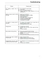
Troubleshooting
17
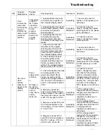
S/N
Possible
Malfunctions
Possible
causes
Checking Steps
Instrument
Solutions
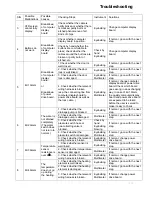
3
VFD screen
cannot fully
display.
Breakdown
of computer
display
board
Check whether the cable is
partly broken or whether there
is cracked, partly burnt or
etched phenomenon of all
kinds of chips.
Eyeballing
Change computer display
board.
Check whether computer
display board in position.
Eyeballing
If normal, go on with the next
step.
4
Buttons do
not work.
Breakdown
of computer
display
board
Check by hand whether the
buttons are comfortable to
press; check whether the
cables around the buttons are
broken or partly burnt or
etched, etc.
Check by
hand
Eyeballing
Change computer display
board.
1 Check whether the door is
well closed.
Eyeballing
If normal, go on with the next
step.
2. Check whether the door
lock is well linked.
Eyeballing
If normal, go on with the next
step.
3. Check whether the door
lock is damaged.
Eyeballing
Multimeter
If normal, go on with the next
step.
5
Err1 Alarm
Breakdown
of computer
display
board.
or
Breakdown
of power
drive board.
4. Check whether the relevant
wiring harness is broken.
(esp. the connecting line from
computer display board to
power drive board as well as
the lock cable. )
Eyeballing
Multimeter
If normal, change computer
display board or power drive
board. Check which board
goes wrong in an exchanging
way. In case of Err1 Alarm,
the quality computer display
board and power drive board
are expected to be taken
before the user is served to
make it easy to check.
1. Check whether the
drainage pump is blocked.
Eyeballing
If normal, go on with the next
step.
2. Check whether the
drainage pump is damaged.
Multimeter
If normal, go on with the next
step.
3. Check whether the
pressure switch hose or
gas-collecting valve is
blocked.
Check by
hand
Eyeballing
blowing
If normal, go on with the next
step.
4. Check whether the
pressure switch is damaged.
Eyeballing
Multimeter
If normal, go on with the next
step.
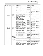
6 Err2
Alarm
The water is
not drained
completely
(The water
switch does
not return to
normal.)
5. Check whether the relevant
wiring harness is broken.
Eyeballing
Multimeter
If normal, change power
drive board.
1. Check whether sensor is
well linked.
Eyeballing
If normal, go on with the next
step.
2. Check whether temperature
sensor is damaged.
Multimeter
If normal, go on with the next
step.
7 Err3
Alarm
Temperature
sensor
resistance is
over 2
Ω
.
3. Check whether the relevant
wiring harness is broken.
Eyeballing
Multimeter
If normal, change power
drive board.
1. Check whether the heating
element is well linked.
Eyeballing
If normal, go on with the next
step.
2. Check whether the heating
element is damaged.
Multimeter
If normal, go on with the next
step.
8 Err4
Alarm
The
temperature
does not go
up during
the heating.
3. Check whether the relevant
wiring harness is broken.
Eyeballing
Multimeter
If normal, change power
drive board.
Summary of Contents for HT1006TXVE
Page 6: ...Safety caution 6 ...
Page 7: ...Safety caution 7 ...
Page 8: ...Safety caution 8 ...
Page 9: ...lnstallation 9 lnstallation 9 ...
Page 10: ...Installation 10 ...
Page 11: ...Functions 11 ...
Page 12: ...Functions 12 ...
Page 13: ...Function schedule 13 ...
Page 14: ...Function schedule 14 Function schedule 14 ...
Page 15: ...Troubleshooting 15 ...
Page 19: ...Wiring circuit 19 ...
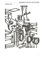
Page 20: ...Exploded view and list of parts 20 Exploded view 78 77 ...

