

29
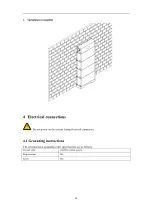
3. If the ventilation and ambient
temperature are normal
,
please
contact the supplier for more
information
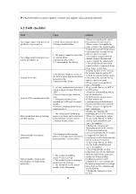
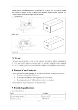
Battery module charging low
temperature protection
1. The product installation
environment is too low
2. The heating film of the battery
module works abnormally
1. Check whether the ambient
temperature exceeds the minimum
allowable charging temperature
range. If the ambient temperature is
too low, please improve the
environment
2.Please contact the supplier for
more information
Automatic shutdown at low battery
voltage
The battery is over-discharged and
not recharged in time
1. The inverter is set with charging
mode, which can charge the battery
through the grid or PV
2. Restart the battery and charge it
through the inverter
3.Please contact the supplier for
more information
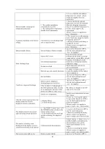
Battery module failure
Internal failure of battery module
Log in to the PowerLite APP to
view the fault information and
contact the supplier
Short discharge time
battery SOC is low
Keep the product charged
continuously and keep the energy
storage battery system fully charged
low ambient temperature
Guarantee the product to work
within the recommended suitable
temperature range
Product overload
Check load status and remove
non-essential loads
Batteries age and capacity decreases
To replace the battery, please
contact the supplier for the battery
and its components
Unable to charge and discharge
Internal failure
Log in to the PowerLite APP to
view the fault information and
contact the supplier
Battery report charging or
discharging protection failure
Log in to the PowerLite APP to
view the fault information and
contact the supplier
After the battery is discharged to
the SOC protection value, it needs
to be charged for a period of time
before it is allowed to discharge.
The battery is charged to the SOC
value set by the restart
battery over temperature
Stand at room temperature for more
than 3 hours
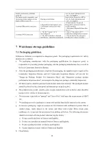
After the system is powered on, the
display cannot be lit or the
displayed content is abnormal
1.Display failure
2.Control module fault
1.Please try restarting the battery
2.Log in to the PowerLite APP to
view the fault information and
contact the supplier
3.Please contact the supplier to
repair or replace the control module
The display cannot wake up and
light up during system operation
1. If the POWER button light is off,
the POWER button is faulty or the
button wiring is loose
2. If the display still does not light
up after restarting, the display is
faulty
1. Log in to the PowerLite APP to
view the fault information
2. Please try restarting the battery
3.Please contact the supplier to
repair or replace the control module
The number of battery icons
displayed on the display screen is
inconsistent with the actual number
Communication disconnection
1.Check whether the battery stack is
installed reliably, and confirm the
abnormal battery through the
battery status indicator on the
display
2. Please try restarting the battery
3.Please contact the supplier to
repair or replace the battery module
The system status light on the
Battery module failure
Log in to the PowerLite APP to


