Haier HHS-1X5K User Manual Download Page 31


28 


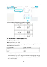
Check the battery system regularly. Contact your support if any anomaly detected. 
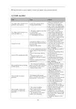
 

6.2


Fault checklist 

Fault 

Cause 

Solution 

No voltage output when power on, 
and the key light is not on 

1. Press the key for less than 3s 
2. Battery module failure 

1.Please try restarting the battery, 
Press the key for more than 3s 
2.Please contact the supplier for 
repair or replace the battery module 

No voltage output when power on, 
but the key light is on 

1. The battery cannot be started due 
to external failure 
2. Battery module failure 
3. Control module fuse blown 

1.Check the external wiring circuit, 
or disconnect the external wiring 
and try to power on again 
2. If it cannot be started after the 
external wiring is disconnected, 
check or replace the battery pack 
3. Check whether the fuse in the 
control module is connected, if not, 
please replace a new fuse. 

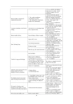
Inverter won't start 

1.The battery voltage is too low or 
the SOC is lower than the shutdown 
protection value 
2.Battery module failure 

1.Charge the battery after starting 
the inverter from the grid or PV 
2.Check the external wiring circuit, 
or disconnect the external wiring 
and try to power on again 
3.Please contact the supplier for 
more information 

Inverter CAN communication fails 

1. Inverter manufacturer's parameter 
setting without setting in PowerLite 
APP; 
2. Inverter battery type selection 
error 
3. Terminal resistance is not 
installed on COM1 port of control 
module 
4. Inverter communication line pin 
connection error 

1.Log in to the PowerLite APP to 
set PCS setting 
2.Select the corresponding battery 
type on the inverter 
3.COM1 install terminal resistor 
4.Check whether the 
communication pin definitions of 
inverter and battery are consistent 
5.Please contact the supplier for 
more information 

Battery shutdown during charging 
and discharging 

1. The charging and discharging 
power is too large, and the battery is 
protected from excessive power 
2. Battery module failure 

1.Reduce the charging and 
discharging power of the inverter; 
2.Please try restarting the battery 
3.Log in to the PowerLite APP to 
view the fault information and 
contact the supplier 

Battery module overcurrent 
protection 

The charging and discharging 
power is too large, and the battery is 
protected from excessive power 

1. Reduce the charging and 
discharging power of the inverter; 
2. Overcurrent fault can be 
recovered automatically. If the fault 
is triggered three times in 
succession, it will be locked and the 
system needs to be restarted 
3.Log in to the PowerLite APP to 
view the fault information and 
contact the supplier 

Battery module charging and 
discharging over-temperature 
protection 

1. The product installation 
environment is too high 
2. The product has been running at 
rated power for too long 
3. The internal fan of the battery 
module works abnormally 

1. Check whether the ambient 
temperature exceeds the maximum 
allowable temperature range and 
whether the battery module 
installation position is well 
ventilated. If it is not ventilated or 
the ambient temperature is too high, 
please improve the ventilation and 
heat dissipation 
2. Reduce the load power of the 
inverter 

Summary of Contents for HHS-1X5K

Page 1: ...User manual Battery energy storage system HHS 1X5K HHS 1X10K HHS 1X15K HHS 1X20K Version 1 0...

Page 2: ......

Page 3: ...allation steps 10 4 Electrical connections 19 4 1 Grounding instructions 19 4 2 Power connector installation 20 4 3 Cable connection 21 4 3 1 Single HHS 1X5K 10K 15K 20K system 21 4 3 2 Multiple HHS 1...

Page 4: ...Prevent from accidental access children and animals Do not step on the product packaging Do not place any foreign objects on top of the battery pack Do not store the battery pack upside down 1 2 Batte...

Page 5: ...k can release toxic gas Keep away from it In case of accidental skin contact wash the skin thoroughly with soap and seek medical advice For eye contact wash under running water 15 minutes and require...

Page 6: ...ial energy storage system with lithium iron phosphate LFP technology Modular design single battery system with 5 to 20kWh 1 4 pcs battery Single battery module is equipped with DC to DC conversion whi...

Page 7: ...1X5K 10K 15K 20K configurations 2 2 Appearance description Appearance of the whole system Figure 2 2 1 Appearance of the whole machine Control module Battery module Mounting the base 5kWh 10kWh 15kWh...

Page 8: ...gure 2 2 3 Right side of the control module Output Positive DC Output Negative DC Parallel communication 0 COM0 Parallel communication 1 COM1 PCS communication RS485 CAN Maintenance LAN Protection ear...

Page 9: ...ion susceptible to flooding Install under shed if possible e For indoor installation 3 feet clearance from doors windows driveway or other batteries Keep away from heating device Prevent from corrosiv...

Page 10: ...irements a Item inspection b Installation clearance c Level control 1000mm 39 37in 915mm 36in 915mm 36in 600mm 24in 600mm 24in 600mm 24in 600mm 24in 0 3 20in 3 20in 3 20in 0 3 20in Wall Floor 20in Bat...

Page 11: ...he outer ones as illustrated below Avoid electricity wire metal conduit or pipe inside the wall consider using wall scanner wall detector 3 2 Installation 3 3 1 Installation tools Impact drill 3 8 13...

Page 12: ...X4 Fixing screws M5 12 X4 Control Module Packaging Components Control module X1 Base X1 L bracket X4 max Fixing screws M5 12 X12 max Expansion screw M8 80 X4 max Self tapping screws M6 60 X4 max M6 18...

Page 13: ...e 3 3 Installation steps a Place the base Take the control module and base module out of the carton and put them side by side The base module should be placed on a level ground parallel to the wall Th...

Page 14: ...tion 1 mounting assembly on Batt No 1 1 mounting assembly on Batt No 2 2 pcs mounting assembly on Batt No 2 Batt No 3 2 pcs mounting assembly on Batt No 2 Batt No 4 c Stack battery module Before stack...

Page 15: ...50kg 110 2lbs Two or more people are necessary Align the connector side first then stack gently to avoid damaging the connector Fasten the installed battery module Fixing screw M5 12 4 pcs Screw cove...

Page 16: ...13 d Adding additional battery module Fasten the stacked battery module Fixing screw M5 12 4 pcs Screw cover plastic 4 pcs...

Page 17: ...shaped bracket against the wall on the L bracket and mark the drilling point Drilling for concrete or brick wall and fixing the L Bracket to the wall Use PE bag from the product packaging to prevent f...

Page 18: ...ping screw must penetrate the stake 38mm 1 Use M6 60 2pcs self tapping screws to drill directly into the stake 2 Use a 13 64 bit to pre drill the holes if there are concrete wall partitions in front o...

Page 19: ...s up to 4 battery modules in total Fasten the stacked battery module Fixing screw M5 12 8 pcs Screw cover plastic 8 pcs g The overall bracket completes the installation position arrangement HHS 1X5K 1...

Page 20: ...te wall Wooden wall HHS 1X5K 10K 15K 20K 15 HHS 1X5K 10K 15K 20K 20 Concrete wall Wooden wall Concrete wall Wooden wall h Control module installation Fasten the stacked battery module Fixing screw M5...

Page 21: ...eck model Tick the nameplate model according to the number of installed battery modules 5kWh HHS 1X5K 10K 15K 20K 5 10kWh HHS 1X5K 10K 15K 20K 10 15kWh HHS 1X5K 10K 15K 20K 15 20kWh HHS 1X5K 10K 15K 2...

Page 22: ...4 Electrical connections Do not power on the system during electrical connection 4 1 Grounding instructions The recommended grounding cable specifications are as follows Ground cable 10AWG yellow gree...

Page 23: ...20 Figure 4 1 1 Schematic diagram of equipment grounding 4 2 Power connector installation...

Page 24: ...igure 4 3 1 Wiring diagram of single machine system No Harness name Cable mark Positive wire harness DC PCS BAT Negative wire harness DC PCS BAT PCS RS485 CAN communication cable BAT PCS 120ohm resist...

Page 25: ...power conductor of the combined HHS 1X5K 10K 15K 20K output shall be according to the total current rated Consider using a distribution box when combining positive and negative output from multiple HH...

Page 26: ...ation wiring of multiple system 5 Power up your system Checked all connections thoroughly before proceeding Refer to user manual for inverter operation 5 1 System power up Close the inverter side swit...

Page 27: ...charging the battery Press and hold the POWER button for more than 8s Disconnect the battery side MCB The system disable output Both Power button led and the display goes off Note Each cluster of batt...

Page 28: ...le fault 5 4 System configuration a Download and install PowerLite APP The battery parameter setting and remote monitoring can be realized through the APP software PowerLite please go to the App Store...

Page 29: ...rner of the main interface to add a site After recommending a power station then add equipment select the SN code on the nameplate of the control module to add And simultaneously click Assigned Plant...

Page 30: ...arge every 6 months From the date of manufacturer shipment the battery shall be maintained every 6 months Action must be taken in case SOC reaches 0 Ambient temperature Must be recharged within 45 50...

Page 31: ...connection error 1 Log in to the PowerLite APP to set PCS setting 2 Select the corresponding battery type on the inverter 3 COM1 install terminal resistor 4 Check whether the communication pin definit...

Page 32: ...fault information and contact the supplier Battery report charging or discharging protection failure Log in to the PowerLite APP to view the fault information and contact the supplier After the batter...

Page 33: ...he packaging manufacturer completes the packaging the supplier needs to apply to the Commodity Inspection Bureau and the Commodity Inspection Bureau will provide the Dangerous Package Product Use Insp...

Page 34: ...not more than 75 The battery pack has a state of charge of 45 to 55 Avoid contact with corrosive substances and keep away from fire and heat sources 8 Dispose of used batteries Comply with applicable...

Page 35: ...18A 24A Maximum discharge current 6 5A 13A 19 5A 25A Dimensions W H D mm 653 597 189 653 912 189 653 1227 189 653 1542 189 Net weight 67kg 119kg 171kg 223kg Rated voltage 400V Operating voltage 350V 4...

Page 36: ...facturer Qingdao Nahui Energy Technology Co Ltd Adress Room303 Entrance 1 No 4 Building Lan Gu Entrepreneurship Center Phase 1 No 7 Keji Yilu Road Aoshanwei Sub district Office Jimo District Qingdao S...

Reviews: