13
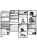
4. With one person holding the back panel, thread the end of the power cord
through the strain relief.
a
b
c
a
UL Listed Strain Relief
b
Back Panel
c
Power Cord
NOTE: Allow enough slack to connect the wires to the terminal block.
f
g
d
e
b
a
c
a
Jumper Wire
b
Terminal Block
c
Ground Screw
d
Power Cord Wires
e
Strain Relief Nut
f
UL Listed Strain Relief
g
Back Panel
5. Remove the green jumper wire from under the ground screw and replace with
the green wire from the power cord and tighten ground screw.
6. Loop the green jumper wire removed from the ground screw back onto its end
that is fastened to the center post of the terminal block.
7. Use 3/8" (1.0 cm) nut driver to connect the neutral (white) wire to the center
terminal block post with one of the 10-32 hex nuts.
8. Using 10-32 hex nuts, connect the red and black wires from the power cord to
the outer posts of the terminal block with the corresponding red and black wires
from the range.
9. Tighten the hex nuts completely, and then verify the connection.
NOTE: For power supply cord replacement, use only a power cord rated at
250 volts minimum, 40- or 50-amps that is marked for use with nominal 13/8"
(3.5 cm) diameter connection opening, with ring terminals and marked for use
with ranges.


