background image

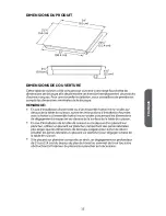
OPENING DIMENSIONS

This cooktop has been designed to accommodate a wide range of cutout sizes to

allow possible replacement with other brands. For a new installation, we recommend

that you consider the minimum dimension of cutout size.

NOTE:

If installing a range hood or microwave hood combination above the

cooktop, follow the range hood or combination microwave hood installation

instructions for the required clearance above the cooktop surface.

When installing the cooktop over a base cabinet, use a base cabinet with

sidewalls wider than the cutout requirements to avoid needing to notch

down the base cabinet sidewalls to clear the cooktop base. 

If the base cabinet has a draw

er, a 5¹⁄₂" (14.0 cm) depth clea

rance from the

top of the countertop to the top of the drawer 

(

or o

ther obstruction) in the

base cabinet is required.

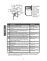
Description

Dimension

(A)

Width of the cooktop

24" (60.9 cm)

(B)

Combustible area above countertop 

19¹⁄₄" (49.0 cm) 19¹⁄₂"

(49.7 cm)

(C)

Minimum clearance between top of cooktop and

bottom of uncovered wood or metal cabinet. 

30" (76.2 cm)

a

(D)

Recommended overhead cabinet depth

18" (45.7 cm) min

(E)

Minimum clearance between front edge of

countertop and front edge of cooktop

2" (5.1 cm)

(F)

Depth of cooktop opening 

20⁵⁄₁₆" (51.7 cm)

(G)

Min. height from countertop to nearest cabinet on

either side of the cooktop

15" (38 cm)

(H)

Junction box: minimum from top of countertop

7" (17.8 cm)

(I)

Junction box: maximum from right side of cabinet

9" (23.0 cm)

4

ENGLISH





 

   

   

    

  

     

   

     





5"

Summary of Contents for HCC2220BEB

Page 1: ...ktop Table de cuisson lectrique radiante de 24 Superficie de cocci n el ctrica radiante de 24 IMPORTANT Save for local electrical inspector s use IMPORTANT Conserver pour consultation par l inspecteur...

Page 2: ......

Page 3: ...ls and Parts 2 Location Requirements 3 Electrical Requirements 5 INSTALLATION INSTRUCTIONS 6 Step 1 Unpack Cooktop 6 Step 2 Prepare for Installation 6 Step 3 Install Cooktop 7 Step 4 Make Direct Wire...

Page 4: ...Read all safety instructions before using the product Failure to follow these instructions may result in re electrical shock serious injury or death...

Page 5: ...built in undercounter use and required cutout dimensions The cooktop must be installed in a level countertop The cooktop should be installed away from strong draft areas such as windows doors fans or...

Page 6: ...ewalls to clear the cooktop base If the base cabinet has a drawer a 5 14 0 cm depth clearance from the top of the countertop to the top of the drawer or other obstruction in the base cabinet is requir...

Page 7: ...2 5 08 cm...

Page 8: ...L CONNECTION REQUIREMENTS INSTALLATION INSTRUCTIONS STEP 1 UNPACK COOKTOP 1 2 3 4 STEP 2 PREPARE FOR INSTALLATION IMPORTANT 1 instructions NOTE 2 NOTE 3 ENGLISH Countertop should be 3 4 2 0cm to 3 7 6...

Page 9: ...e of the countertop If you need to reposition the cooktop lift the entire cooktop from the opening to avoid scratching the countertop 3 Working from underneath the cooktop base remove the clamping bra...

Page 10: ...your cooktop complete electrical connections according to local codes and ordinances WARNING Electrical Shock Hazard Disconnect power before servicing Use 8 gauge copper wire Electrically ground cook...

Page 11: ...stallations 1996 NEC mobile homes and recreational vehicles or in an area where local codes prohibit grounding through the neutral conductor For installations where grounding through the neutral condu...

Page 12: ...UL listed wire connector 5 Connect the neutral white wire C from the house electrical supply to the ground green or bare wire D from the cooktop cable using a UL listed wire connector 6 Connect the 2...

Page 13: ...nector G 7 Attach a UL listed wire connector to the neutral white wire H from the house electrical supply 8 Gently tuck the wire connections into the junction box and install the junction box cover ST...

Page 14: ...Exigences d emplacement 14 Sp cifications lectriques 17 INSTRUCTIONS D INSTALLATION 18 tape 1 D ballage de la table de cuisson 18 tape 2 Pr paration pour installation 18 tape 3 Installation de la tab...

Page 15: ...Lisez toutes les consignes de s curit avant d utiliser le produit Le non respect de ces recommandations comporte un risque de d lectrocution et de blessures graves voire mortelles...

Page 16: ...Assurez vous que les placards et les rev tements muraux pr sents proximit de la table de cuisson peuvent supporter des hautes temp ratures jusqu 93 C g n r es par la table de cuisson Veillez toujours...

Page 17: ...DIMENSIONS DU PRODUIT DIMENSIONS DE L OUVERTURE REMARQUE FRAN AIS...

Page 18: ...e de jonction minimum partir du dessus du plan de travail 7 17 8 cm I Bo te de jonction maximum partir de la droite du placard 9 23 0 cm J Largeur de la d coupe de la table de cuisson 23 58 7 cm K D g...

Page 19: ...et le calibre des fils sont appropri s et en conformit avec le National Electrical Code ANSI NFPA n 70 derni re dition et avec tous les codes et r glements locaux On peut obtenir un exemplaire de la...

Page 20: ...ATION TAPE 1 D BALLAGE DE LA TABLE DE CUISSON 1 2 3 4 TAPE 2 PR PARATION POUR INSTALLATION IMPORTANT 1 REMARQUE 2 renseignements REMARQUE 3 FRAN AIS Le comptoir devrait tre d une paisseur comprise ent...

Page 21: ...TAPE 3 INSTALLATION DE LA TABLE DE CUISSON 1 REMARQUE a b c A B C 2 REMARQUE travail 3 4 FRAN AIS...

Page 22: ...5 a c b A B C 6 b a c d e f A B C D E F 7 TAPE 4 RACCORDEMENT LECTRIQUE DIRECT FRAN AIS...

Page 23: ...vice de r paration agr Cet appareil est fabriqu avec un conducteur de TERRE vert connect au ch ssis du la table de cuisson Apr s vous tre assur qu il n y a plus de courant branchez le conduit flexible...

Page 24: ...nducteur neutre est interdit se reporter au sch ma Neutre non reli la terre Pour raccorder l appareil la terre utiliser le conducteur ou la borne de mise la terre Connecter de la mani re habituelle le...

Page 25: ...au conducteur de liaison la terre vert ou nu D du c ble de la cuisini re au moyen d un connecteur de fils homologu UL 6 Connecter ensemble les 2 connecteurs rouges G avec un connecteur de fils homolo...

Page 26: ...on UL 6 Raccorder les 2 conducteurs de liaison la terre verts ou nus F au moyen d un connecteur de fils G homologu UL 7 Relier un connecteur de fils homologu UL au conducteur neutre blanc H de l alime...

Page 27: ...fusibles du domicile sont intacts et serr s le disjoncteur n est pas d clench La cuisini re est branch e sur une prise reli e la terre La prise de courant est correctement aliment e Demander un lectri...

Page 28: ...tos de ubicaci n 28 Requisitos el ctricos 31 INSTRUCCIONES DE INSTALACI N 32 Paso 1 Desempaque la superficie de cocci n 32 Paso 2 Prep rese para la instalaci n 32 Paso 3 Instale la superficie de cocci...

Page 29: ...Lea todas las instrucciones de seguridad antes de usar el producto El incumplimiento de estas instrucciones puede provocar un incendio descargas el ctricas lesiones graves o la muerte...

Page 30: ...un instalador cali cado o por un t cnico de servicio Aseg rese de que los gabinetes y los revestimientos de las paredes alrededor de la estufa puedan soportar las temperaturas hasta 200 F generadas p...

Page 31: ...DIMENSIONES DEL PRODUCTO MEDIDAS DE LA ABERTURA NOTA ESPA OL...

Page 32: ...A B C a D armario E cocci n F cocci n G cocci n H I J K L a ESPA OL 5 Permita un espacio vertical m nimo de 5 desde la profun didad m nima del fondo de la estufa desde cualquier super cie de combusti...

Page 33: ...el ctrica y el tama o de los alambres sean adecuados y de conformidad con el National Electrical Code C digo Nacional El ctrico ANSI NFPA 70 ltima edici n y con todos los c digos y ordenanzas locales...

Page 34: ...CCIONES DE INSTALACI N PASO 1 DESEMPAQUE LA SUPERFICIE DE COCCI N 1 2 3 4 impreso PASO 2 PREP RESE PARA LA INSTALACI N IMPORTANTE 1 NOTA 2 NOTA 3 ESPA OL La encimera debe ser de 3 4 2 0cm a 3 7 6cm de...

Page 35: ...PASO 3 INSTALE LA SUPERFICIE DE COCCI N 1 NOTA a b c A cocci n B C 2 NOTA 3 4 ESPA OL...

Page 36: ...5 a c b A B C 6 b a c d e f A B C D E abrazadera F 7 PASO 4 REALICE UNA CONEXI N EL CTRICA POR CABLE DIRECTO ESPA OL...

Page 37: ...e aparato est fabricado con un alambre verde de CONEXI N A TIERRA conectado al chasis de la placa de cocci n Despu s de asegurarse de haber desconectado la energ a conecte el conducto flexible desde e...

Page 38: ...rohibida la puesta a tierra a trav s del conductor neutro vea el gr co del conductor neutro sin puesta a tierra Use el terminal a tierra o conductor de la unidad a tierra Conecte el terminal neutro o...

Page 39: ...cable neutro de color blanco C proveniente del suministro el ctrico del hogar con el cable de puesta a tierra de color verde o sin recubrimiento D proveniente del cable de la estufa usando el conector...

Page 40: ...sando un conector de alambres que est en la lista de UL 6 Conecte los 2 cables de puesta a tierra de color verde o sin recubrimiento F juntos usando un conector de alambres G que se encuentre en la li...

Page 41: ...asa est intacto y ajustado o que no se haya disparado el cortacircuitos Que la estufa est enchufada en un tomacorriente con conexi n a tierra Que el suministro el ctrico est conectado P ngase en conta...

Page 42: ......

Page 43: ......

Page 44: ...ateurs Haier Customer Satisfaction Center au 1 877 337 3639 UNE PREUVE D ACHAT DATEE EST REQUISE POUR BENEFICIER DE LA GARANTIE IMPORTANTE No regrese este producto a la tienda Si tiene alg n problema...

Reviews: