Manuale di Installazione Uso e Manutenzione - Installation, Use and
Maintenance Manual
pag. 22
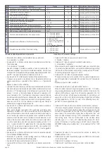
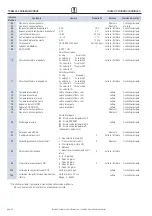
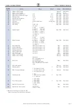
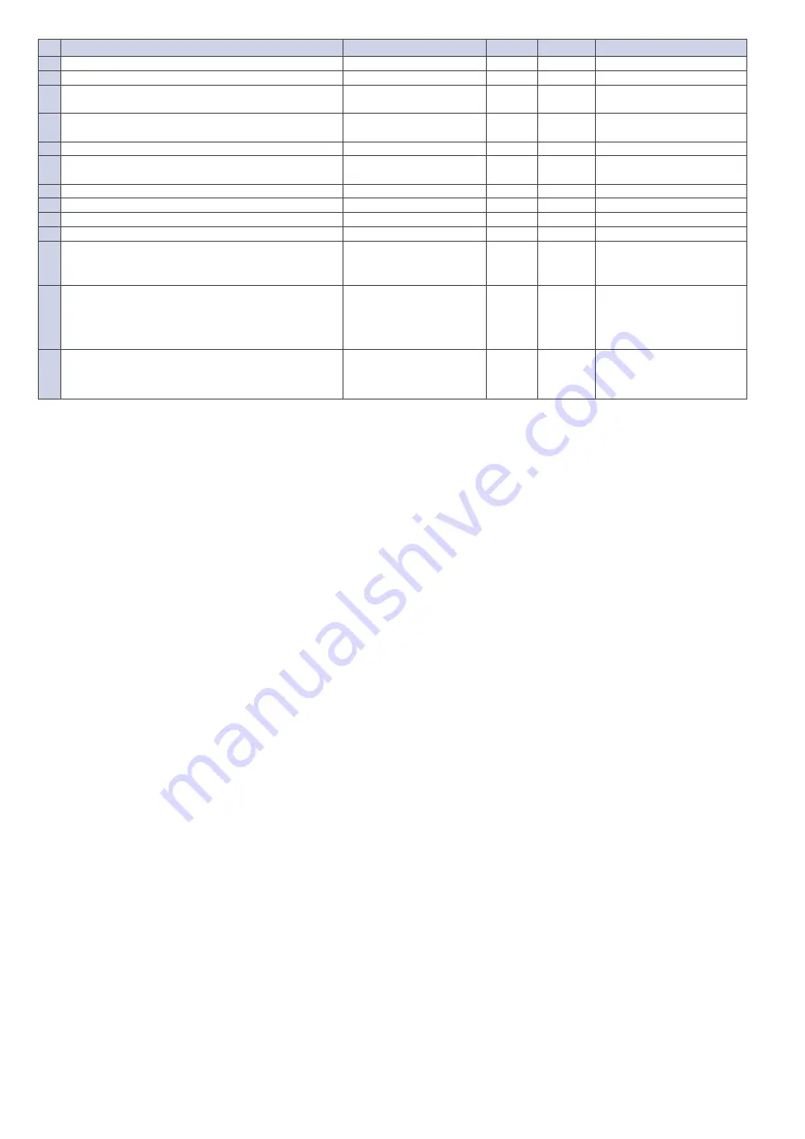
No.
Contenuto /
Contents
Range
Default
Unit
Posizione /
Record Position
00
Funzione di riavvio automatico /
Power to auto restart
0-1
1
Scheda elettronica /
Main PCB
01
Riscaldatore elettrico disponibile /
Electrical heater available
0-1
0
Scheda elettronica /
Main PCB
02
Temperatura di apertura by-pass X
By pass opening temperature X
5-30
19
°C
Scheda elettronica /
Main PCB
03
Temperatura di apertura by-pass Y
By pass opening temperature Y
2-15
3
°C
Scheda elettronica /
Main PCB
04
Intervallo di sbrinamento
/ Defrost interval
15-99
30
Minute
Scheda elettronica /
Main PCB
05
Temperatura di inizio dello sbrinamento
Defrost entering temperature
-9….+5
-1
°C
Scheda elettronica /
Main PCB
06
Tempo di durata sbrinamento /
Defrost duration time
2-20
10
Minute
Scheda elettronica /
Main PCB
07
Valore della funzione CO2 /
CO2 sensor function value
80-250
00
PPM
Scheda elettronica /
Main PCB
08
Indirizzo ModBus /
ModBus address
1-16
1
Scheda elettronica /
Main PCB
21
ERV selezione modelli /
ERV models match/selection
0-9
Scheda elettronica /
Main PCB
23
Controllo velocità della ventola
/ Fan speed control
0 = 2 velocità /
speeds
1 = 3 velocità /
speeds
2 = 10 velocità /
speeds (DC)
2
Scheda elettronica /
Main PCB
24
Impostazione multifunzione
/ Multifunction setting
0 = Nessuno /
None
1 = Reset timer funzionamento
ventilatore /
Reset timer of fan
operation
2…5 = Riservato / Reserved
0
25
Impostazione allarme filtro
/ Filter alarm setting
0 = 45 giorni /
days
1 = 60 giorni /
days
2 = 90 giorni /
days
3 = 180 giorni /
days
0
Scheda elettronica /
Main PCB
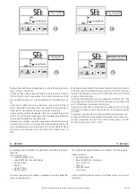
Istruzione delle impostazioni dei parametri
• Parametro 00 si riferisce alla modalità di riavvio automatico:
0: non abilitato, 1: abilitato.
• Il parametro 01 si riferisce alla funzione di riscaldamento elettrico del-
l'aria di mandata
0: non presente 1: presente.
Quando si collega il riscaldatore elettrico all'aria di mandata (SA), l'u-
tente deve scegliere 1 per attivare il riscaldatore elettrico, e nella visua-
lizzazione SA la temperatura SA può essere impostata premendo i tasti
▲
e
▼
. Il range di temperatura di taratura è di 10-25 ° C.
• Il parametro 02-03 si riferisce alla funzione di bypass automatico.
Il bypass viene aperto a condizione che la temperatura esterna sia
uguale o superiore a x (parametro 02) e inferiore a x + Y (parametro
03).
Bypass è chiuso in altre condizioni.
• I parametri 04-06 si riferiscono alla funzione di sbrinamento automatico.
Quando la temperatura di espulsione EA dello scambiatore di calore é
inferiore a -1°C (temperatura di inizio sbrinamento, parametro 05) per
almeno 1 minuto, e l’intervallo tradue sbrinamenti é superiore a 30
minuti (parametro 04), il ventilatore di espulsione viene portato alla
massima velocità per effettuare lo sbrinamento, mentre il ventilatore di
rinnovo viene spento. Questa fase dura finché la temperatura di espul-
sione non vale T 05 + 15°C per almeno un minuto, oppure il tempo di
sbrinamento é maggiore del parametro 06.
• Il parametro 07 si riferisce alla funzione di controllo della concentrazio-
ne di CO
2
(opzionale).
Dopo aver collegato il sensore di CO
2
opzionale, sul display viene
visualizzato il simbolo CO
2
. Se la concentrazione di CO
2
è superiore al
valore di impostazione, allora l’unità lavorerà alla massima portata d’a-
ria; se l’unità è già in alta velocità quando la concentrazione di CO
2
è
superiore al set impostato, essa mantiene la velocità massima in ese-
cuzione. Se il valore misurato diminuisce sotto al valore di impostazio-
ne, allora l’unità ritorna allo stato precedente (standby, velocità 1, 2, 3
ecc.). Il valore di set di CO
2
predefinito è 00, il che significa funzione
di CO
2
off. La gamma di regolazione è 80-250, che significa 800-
2500PPM (valore di regolazione moltiplicato per 10), il set suggerito è
di 1000 PPM.
• Il parametro 08 si riferisce alla funzione di controllo centrale per identi-
ficare l'indirizzo ModBus dell’Unità.
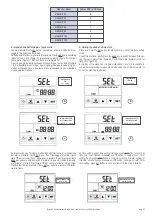
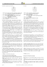
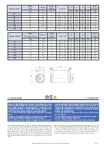
• Parametro 21 permette i corretti settaggi adatti su PCB alla taglia
dell’Unità, fare riferimento alla tabella seguente.
• Il parametro 23 deve essere rilasciato al valore 2.
• I parametri 24 e 25 sono privi di significato e non devono essere modi-
ficati.
Instruction of Parameter Settings
•
Parameter 00 refers to power to auto restart mode
0: Disable, 1: Enable.
•
Parameter 01 refers to supply air electrical heater function
0: not available 1: available.
When connecting with supply air electrical heater, user should choose
1 to activate the electrical heater, and under the SA temperature setting
interface, the SA temperature can be set by pressing
▲
and
▼
button.
The setting temperature range is 10 - 25° C.
•
Parameter 02 - 03 refers to automatic bypass function
The bypass is opened on the condition that the outdoor temperature is
equal or higher than X (parameter 02) and less than X+Y (parameter
03).
Bypass is closed on other conditions.
•
Parameters 04-06 refer to automatic defrost function.
When EA sideof heat exchanger temperature lower than -1°C (defro-
sting entering temperature, parameter 05) and last for 1 minute, and the
interval of defrosting is longer than 30 minutes (parameter 04), the
exhaust fan will run at high speed automatically for defrosting, and
supply fan will stop, until EA side temperature higher than defrosting
entering tempe15°C for 1 minute, or the defrosting time is lon-
ger than 10 minutes (parameter 06).
•
Parameter 07 refers to CO
2
concentration control function (optional)
After connecting the optional CO
2
sensor, the CO
2
symbol will display
on the screen. If CO
2
concentration is higher than setting value, the unit
will work at the maximum air flow rate; if the unit is already in highest
speed when CO
2
concentration higher than setting value, then unit
keeps the highest speed running. If CO
2
concentration reduces lower
than setting value, then unit returns back to the previous status
(standby, speed 1, 2, 3 etc.). CO
2
default setting value is 00, which
means CO
2
function off. setting range is 80-250, which means 800-
2500PPM (setting value multiply then 10), recommend SET is 1000
PPM.
•
Parameter 08 refers to the central control function to identify the
ModBus address of Unit.
•
Parameter 21 to match the suitable program on PCB to the Unit model,
refer to below table.
•
Parameter 23 must leave to 2 value.
•
Parameter 24 and 25 have nominig and must not be modified.
Summary of Contents for HACI-RP Series
Page 36: ...2019 05 ...


