background image

Manuale di Installazione Uso e Manutenzione - Installation, Use and

Maintenance Manual

pag. 30

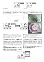
Il Sensore di umidità è fornito completo di cavo lungo 5 metri e connettori
per il collegamento alla scheda elettronica a bordo macchina. Se neces-
sario, si può utilizzare un cavo più lungo a carico dell’installatore (limiti e
caratteristiche nel precedente paragrafo). Si veda il capitolo 11 per i det-
tagli della connessione alla scheda elettronica.
Il dispositivo va installato nell’ambiente di maggior frequentazione delle
persone e dove é necessario controllare il valore dell’umidità.
Se il valore di umidità è superiore al valore impostato, allora l’unità lavo-
rerà alla massima portata d’aria; se l’unità è già in alta velocità quando l’u-
midità è superiore al set impostato, essa mantiene la velocità massima in
esecuzione. Se il valore misurato diminuisce sotto al valore di impostazio-
ne, allora l’unità ritorna allo stato precedente (standby, velocità 1, 2, 3
ecc.). 

Attenzione: l’unità rimane accesa finchè il valore di umidità non
scende sotto il set, anche con comando OFF da pannello.

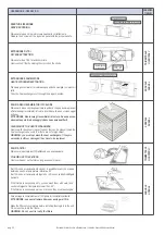
Silenziatore circolare a canale - SLC

E’ fornito a corredo nella misura compatibile al diametro dei condotti di col-
legamento dell’unità. Montaggio a canale a cura dell’installatore con ade-
guato staffaggio a parete o soffitto.

Modulo di sanificazione BIOXIGEN®

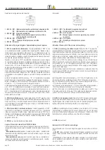
BIOX

E’ fornito a corredo nella misura compatibile al diametro dei condotti di col-
legamento dell’unità. Montaggio a canale a cura dell’installatore. Per il
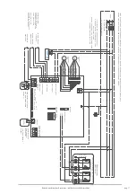
cablaggio seguire lo schema elettrico sotto indicato; tenere conto di una
massima potenza assorbita pari a 20 W.

The humidity  sensor comes complete with a 5 metre long cable and con-
nectors for connection to the electronic board on the machine. If neces-
sary, a longer cable can be used to load the installer (limits and specifica-
tion in the previous paragraph). See Chapter 11 For details of the con-
nection to the electronic card.
The device should be installed in the room where live most of people and
where it is necessary to control the value of humidity.
If humidity is higher than setting value, the unit will work at the maximum
air flow rate; if the unit is already in highest speed when the humidity level
is higher than setting value, then unit keeps the highest speed running. If
humidity level reduces lower than setting value, then unit returns back to
the previous status (standby, speed 1, 2, 3 etc.).

Warning: the unit keeps ON as long as the humidity level will not
drop under the set, even though the unit is switched OFF by the con-
troller.

Duct circular sound attenuator - SLC

It is supplied as a kit; connections diameter are in conformity to the unit.
Duct mounting by the installer assembly with adequate fixing system to
wall or ceiling.

Purifying system BIOXIGEN®  -BIOX

It is supplied as a kit; connections diameter are in conformity to the unit.
Duct mounting by the installer assembly with adequate fixing system to
wall or ceiling. For the wiring see the electrical scheme below; maximum
power supply 20 W.

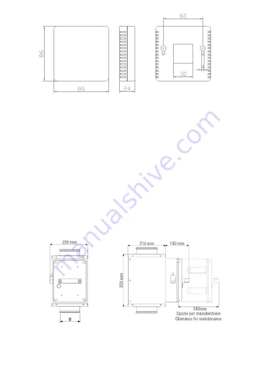
Sensore umidità - USW

Humidity sensor - USW

Modulo di riscaldamento elettrico SBE1 / SBE2

Elemento del tipo corazzato completo di termostati di sicurezza e relè
di comando, è gestita dal controllore della macchina, inserito in involu-
cro in lamiera zincata per applicazione esterna.

SBE1

modulo di pre-riscaldamento monostadio con funzione di sbrina-

mento; 

SBE2

modulo di post-riscaldamento bi-stadio.

Electric heating module SBE1 / SBE2 

Finned pipe coil with safety thermostats enclosed between galvanized
steel plates with duct round adapters downstream and upstream, to be
placed externally. 

SBE1

one stage pre-heating module with defrost function;

SBE2

two stage post-heating module.

Summary of Contents for HACI-RP Series

Page 1: ...HACI RP 25 130 ErP 2018 UNITÀ DI RECUPERO CALORE HEAT RECOVERY UNITS MANUALE DI INSTALLAZIONE USO E MANUTENZIONE INSTALLATION USE AND MAINTENANCE MANUAL ...

Page 2: ...LEGAMENTI ELETTRICI 15 11 1 Schemi Elettrici 16 11 2 Scheda Elettronica di Controllo e Potenza 18 12 MESSA IN SERVIZIO 18 13 PANNELLO DI COMANDO 19 14 ISTRUZIONI D USO 19 15 MODBUS 25 16 INTRODUZIONE DEL SELETTORE 28 17 INSTALLAZIONE ACCESSORI 29 18 MANUTENZIONE 31 19 LOCALIZZAZIONE DEI GUASTI 33 20 SMALTIMENTO 33 21 PARTI DI RICAMBIO 34 INDICE 1 SYMBOLS USED 3 2 WARNINGS AND GENERAL RULES 3 EC De...

Page 3: ...ntenance interventions must be carried out by authorised staff or staff qualified according to that envisioned by this book Do not modify or tamper with the appliance as dange rous situations can be created and the appliance manufacturer will not be liable for any damage caused Dopo aver tolto l imballo assicurarsi dell integrità e della completezza del contenuto In caso di non rispondenza rivolge...

Page 4: ...en the doors for accessing the internal parts of the appliance without first having switched off the master switch of the system È vietato disperdere abbandonare o lasciare alla portata di bambini il materiale dell imballo in quanto può essere potenziale fonte di pericolo It is prohibited to disperse abandon or leave the packing mate rials within the reach of children as they are a potential sourc...

Page 5: ... 2 2 1 8 4 8 70 B276 7 758 2 24 44 62 C 2 6 24 B276 2 2 7 1 78 6 42 5 6 6 7 1 7 6 24 7 A 76 5 126 A 2 2 7 1 78 6 42 5 6 6 7 1 7 6 24 7 A 76 1 88 7 25 276 7 1 4 7 1 5 4 260 7 4 75 06 2 758 2 242 A 2 2 7 1 78 6 42 5 6 6 7 1 7 6 24 7 A 76 1 1 5762 276 7 1 4 7 5 4 260 7 4 2 4 9 285 6 206 7 2 126 26 74 0 4252 2 2 7 1 78 6 42 5 6 6 7 1 7 6 24 7 6 76 1 2 276 7 1 7 1 B 7 6 26 4 2 4 6 4 762 9 285 6 7 2 2 7...

Page 6: ... THE UNIT The units feature a rating plate that describes the following A Mark of the manufacturer B Address of the manufacturer C Unit model D Unit serial number E Voltage number of phases frequency of the power supply F Max absorbed current G Unit code H Manufacturinga date I CE mark PER EVENTUALI RICHIESTE DI INFOMAZIONI E NECESSARIO RIVOLGERSI ALLA SEDE COMUNICANDO IL NUMERO DI SERIE DELL UNIT...

Page 7: ...ch Screen PTS Sensore di CO2 da parete QSW Sensore di umidità da parete USW Silenziatore circolare a canale SLC Modulo di sanificazione BIOXIGEN BIOX Modulo di pre riscaldamento elettrico SBE1 Modulo di post riscaldamento elettrico SBE2 PTS QSW BIOX USW 4 CARATTERISTICHE TECNICHE 4 TECHNICAL FEATURES Air to air enthalpy heat recovery device thermal efficiency up to 76 Galvanized steel self support...

Page 8: ...ECUPERATORE DI CALORE HEAT EXCHANGER Efficienza termica invernale Winter thermal effic 3 73 0 74 0 76 0 74 0 76 0 76 0 74 2 Efficienza entalpica invernale Winter enthalpy effic 3 65 0 65 0 67 0 65 0 65 0 62 0 59 0 Efficienza termica estiva Summer thermal effic 4 73 0 74 0 76 0 74 0 76 0 76 0 74 0 Efficienza entalpica estiva Summer enthalpy effic 4 62 0 62 0 63 0 60 0 63 0 60 0 58 0 Efficienza term...

Page 9: ...15 111 270 315 111 111 142 142 30 33 1070x755x350 6 HACI RP 35 804 814 100 150 675 862 19 855 480 111 270 480 111 111 162 162 37 41 1070x960x350 6 HACI RP 50 904 894 107 200 754 960 19 955 500 135 270 500 135 135 202 202 43 47 1125x1060x350 6 HACI RP 65 884 1186 85 250 1115 940 19 945 428 170 388 428 170 170 228 228 65 70 1390x1055x455 5 HACI RP 80 1134 1186 85 250 1115 1190 19 1200 678 170 388 67...

Page 10: ...RIER AND MUST BE PERFORMED USING STRAPS OR ROPES SO AS TO AVOID DAMAGING THE PACKAGING 8 TRASPORTO 8 TRANSPORT PER LA MOVIMENTAZIONE UTILIZZARE IN FUNZIONE DEL PESO MEZZI ADEGUATI COME PREVISTO DALLA DIRETTIVA 89 391 CEE E SUCCESSIVE MODIFICHE WHEN HANDLING THE UNITS USE SUITABLE MEANS ACCORDING THE WEIGHTS INVOLVED AS ENVISAGED BY EC DIRECTIVE 89 391 AND SUBSEQUENT AMENDMENTS LA DITTA COSTRUTTRIC...

Page 11: ...R DANNI CAUSATI DA UN USO IMPRO PRIO DELL UNITÀ E O DA MODIFICHE ESEGUITE SENZA AUTORIZ ZAZIONE THE MANUFACTURER DECLINES ALL RESPONSIBILITY FOR THE FAILURE TO COMPLY WITH THE SAFETY AND ACCIDENT PRE VENTION STANDARDS DESCRIBED BELOW IT ALSO DECLINES ALL LIABILITY FOR DAMAGE CAUSED BY IMPROPER USE OF THE UNIT AND OR MODIFICATIONS PERFOR MED WITHOUT AUTHORISATION L INSTALLAZIONE DEVE ESSERE EFFETTU...

Page 12: ...nt of components such as coils filters etc If the unit is hung from the ceiling all the sections that make up the air handling unit must be connected to the ceiling 10 3 INFORMAZIONI PRELIMINARI Operare rispettando le norme di sicurezza in vigore accertandosi della sufficiente libertà di movimento e della pulizia degli ambienti di installazione Usare idoneo abbigliamento antinfortunistico e dispos...

Page 13: ...uatamente i condotti per evitare dispersioni termiche e formazione di condensa Condotto esterno dell aria di rinnovo Outside Fresh air duct Condotto di aria fresca Fresh air duct Barra di sospensione Suspending Pole Aria di mandata Supply Air Aria di ripresa Return Air Condotto aria di ripresa Return Duct Aria di espulsione Exhaust Duct Out Isolamento Insulation Condotto di espulsione Discharge Du...

Page 14: ...ndio 8 Per evitare ricircolo tra l aria espulsa e l aria di rinnovo la distanza tra le due aperture installate sulla parete esterna deve essere supe riore a 1000 mm Curve a gomito Serve bends Bruschi cambi di direzione Multiple direction changes Bruschi ristrengimenti o schiacciature Multiple reducers Crimped duct Temperatura bulbo secco C Dry Ball Temp C Umidità assoluta Kg Kga s Absolute Humidit...

Page 15: ...ggio allentata o errata può causare esplosioni o incendi quando l unità inizia a funzionare Usare solo tensione nominale di alimentazione Non installare spostare o reinstallare l unità da soli Un azione impropria può causare instabilità dell unità scosse elettriche o incendi Il funzionamento dell unità continuamente in uno stato ano malo può causare guasti scosse elettriche o incendi Non mettere l...

Page 16: ...GND black Vcc white 0 6 4 2 Vcc white 0 6 4 2 2 0 2 1 0 4 0 2 0 A TRATTEGGIO SONO RAPPRESENTATI I COLLEGAMENTI DA EFFETTUARSI A CURA DELL INSTALLATORE DASHED LINES SHOW THE CONNECTIONS TO BE CARRIED OUT BY THE INSTALLER 5 201 02 6 6 00 1 1 2 16 0 0 04 1 Differential pressure switch RA Probe FR EA Probe OA Probe SA Probe CO2 Probe Control Panel 7 CONTROL PANEL Option 4 1 FILTERS PRESSURE SWITCH 7 M...

Page 17: ... A TRATTEGGIO SONO RAPPRESENTATI I COLLEGAMENTI DA EFFETTUARSI A CURA DELL INSTALLATORE DASHED LINES SHOW THE CONNECTIONS TO BE CARRIED OUT BY THE INSTALLER 1 5 4 1 0 Vm red GND black Vcc white 5 3 1 Vcc white 5 3 1 1 1 0 5 3 1 0 1 3 0 RA Probe OA Probe FR EA Probe SA Probe CO2 Probe 0 1 05 3 0 0 0 6 0 3 FILTERS PRESSURE SWITCH 6 CONTROL PANEL Option Max speed 12V A B GND Porta Modbus RS485 Modbus...

Page 18: ...quindi il by pass si chiuderà automaticamen te Si prega di fare attenzione che il passaggio da by pass aperto chiu so sarà di circa 1 minuto in ritardo Check that all cable sizes circuit breakers and wire connections are correct before following below commissioning steps 1 Press button to turn on off the ventilator 2 Match the correct speed to ERV The parameter that identifies the size of the unit...

Page 19: ...m Filter Allarm Tipo di Temperatura Temperature type Velocità Ventola Fan Speed Riparazione Repair Modalità auto Auto Mode By pass By Pass Spento OFF State Acceso ON State Stato di Blocco LOCK State Stato di Sblocco UNLOCK State OA aria esterna RA aria di ripresa ambiente da trattare EA aria di espulsione SA aria di mandata verso l ambiente da trattare OA outdoor air or fresh air RA return room ai...

Page 20: ...ir temperature by pressing and button The set ting temperature range is 10 25 C A If 0 C setting temperature minus SA temperature 5 C Then 1st stage heater on 2nd stage heater off B If Setting temperature minus SA temperature 5 C Then 1st and 2nd stage heater on The CO2 symbol appears when the CO2 sensor is connected ERV runs at boost speed when CO2 concentration higher than setting value The humi...

Page 21: ...Dopo aver scelto il numero di parametro corect premere il tasto MODE per breve il valore del parametro lampeggia nell angolo in alto a destra in questo momento per cambiare il valore con il tasto e per salvare Attenzione Dopo l impostazione parametri il sistema ha bisogno di circa 15 secondi per registrare durante questo periodo l alimentazione non deve essere spenta Per impostare i parametri appr...

Page 22: ...o ne di CO2 opzionale Dopo aver collegato il sensore di CO2 opzionale sul display viene visualizzato il simbolo CO2 Se la concentrazione di CO2 è superiore al valore di impostazione allora l unità lavorerà alla massima portata d a ria se l unità è già in alta velocità quando la concentrazione di CO2 è superiore al set impostato essa mantiene la velocità massima in ese cuzione Se il valore misurato...

Page 23: ...uto il tasto SET per sei secondi per entrare in modalità di set taggio di impostazione del tempo Sotto questa interfaccia premere brevemente il tasto MODE per passare da impostazione orario figura A impostazione giorno figura B ON per fasce orarie figura C OFF per fasce orarie figura D Ogni singolo giorno della settimana dispone di due fasce orarie chiamate 1 e 2 è possibile impostare per ogni sin...

Page 24: ...nostro esempio Attenzione quanto fatto finora equivale a far accendere l unità alle ore 12 00 del lunedì ma fino ad ora nessun orario di spegnimento OFF è stato impostato Con analogo procedimento è possibile impostare l orario di ON per tutte le fasce desiderate Se si desidera una volta eseguita una impostazione modificare soltanto l o rario di alcune fasce vale la pena sottolineare che quando si ...

Page 25: ...OFF D Setting the time to switch off all the daily time slots both slot 1 and slot 2 In the same way as described in the above point set the OFF time for all the time slots taking care to select the D figure that is the OFF time slot setting as the starting point It is worth remembering that if you have selected as ON time for the 1 time slot on Monday the time of 12 00 the OFF time to be set for ...

Page 26: ...nte valore misurato offset 40 Lettura Controllo principale 13 Temperatura esterna valore misurato offset 40 Lettura Controllo principale 14 Temperatura aria di scarico valore misurato offset 40 Lettura Controllo principale 15 Temperatura di sbrinamento valore misurato offset 40 Lettura Controllo principale 16 Segnale esterno ON OFF valore interrogato Lettura Controllo principale 17 Segnale CO2 ON ...

Page 27: ...e Main Control 12 Room temperature observed value offset 40 Read Main Control 13 Outdoor temperature observed value offset 40 Read Main Control 14 Exhaust air temperature observed value offset 40 Read Main Control 15 Defrosting temperature observed value offset 40 Read Main Control 16 External ON OFF signal query value Read Main Control 17 CO2 ON OFF signal query value Read Main Control 18 Useless...

Page 28: ...gnale in tensione per attivare il recuperatore Si possono avere 2 situazioni allorché viene chiuso il con tatto Recuperatore spento quando il contatto viene chiuso i ventilatori fun zioneranno ad alta velocità quando il contatto esterno si apre il recupe ratore ritorna in OFF Recuperatore acceso quando il contatto viene chiuso i ventilatori si portano alla massima velocità quando il contatto viene...

Page 29: ...postazione allora l unità ritorna allo stato precedente standby velocità 1 2 3 ecc Attenzione l unità rimane accesa finchè il valore di concentrazione non scende sotto il set anche con comando OFF da pannello Per ulteriori dettagli vedere pag 22 CO2 wall mount sensor QSW The CO2 sensor comes complete with a 5 metre long cable and con nectors for connection to the electronic board on the machine If...

Page 30: ...neces sary a longer cable can be used to load the installer limits and specifica tion in the previous paragraph See Chapter 11 For details of the con nection to the electronic card The device should be installed in the room where live most of people and where it is necessary to control the value of humidity If humidity is higher than setting value the unit will work at the maximum air flow rate if...

Page 31: ... 2 Soltanto il personale assegnato e precedentemente addestrato e qualificato può effettuare le operazioni di manutenzione 3 Se l unità deve essere smontata proteggere le mani con guanti BEFORE UNDERTAKING WHICHEVER MAINTENANCE OPERATION MAKE SURE THAT THE MACHINE IS SWITCH OFF AND THAT IT CAN NOT BE ACCIDENTALLY CONNECTED TO THE POWER IT IS THEREFORE NECESSARY TO CUT OFF THE ELECTRIC SUPPLY DURIN...

Page 32: ...ARNING you must not wash the heat exchangers If they are excessively dirty or damaged they have to be replaced ANNUALE ANNUAL PULIZIA FILTRI Rimuovere la polvere dai filtri utilizzando un aspirapolvere WASHING OF THE FILTERS Remove the dust on the filters using a vacuum cleaner TRIMESTRALE QUARTERLY Se i filtri sono eccessivamente sporchi è possibile lavarli con acqua e detersivo neutro a temperat...

Page 33: ... ruota al contrario The rotor turn backwards Rumore Noise Flusso d aria eccessivo Excessive air flow Trafilamenti d aria dai giunti dei canali per mancata sigillatura o fessurazioni Air leakage from the duct joints Ventola sbilanciata Unbalanced fan Corpi estranei all interno Foreign bodies in the case Forti vibrazioni Strong vibrations Girante sbilanciata a causa di usura o di deposito di polvere...

Page 34: ...Manuale di Installazione Uso e Manutenzione Installation Use and Maintenance Manual pag 34 21 PARTI DI RICAMBIO 21 SPARE PARTS ...

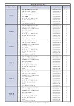
Page 35: ...OARSE 50 COARSE 50 Filter CF0P30MICH050050 2 15 Filtro ePM2 5 95 ePM2 5 95 Filter CF0M90MICH050480 2 12 By pass MV00BYP0MICH0000 1 14 Scheda elettronica di controllo PCB CT00000MICEH0250 1 HACI RP 65 1 Flangia circolare di raccordo canale Spigot MV00BOC0MICH0800 4 3 Scatola copertura Q E Electrical box CP04V00MICROEH00 1 4 Recuperatore di calore Plate heat exchanger PR000E000MICH065 2 8 Motore Mot...

Page 36: ...2019 05 ...
Reviews: